ProtoMAX®
Maintenance Guide
|
Hypertherm, Inc. |
|
Information:
|
info@protomax.com |
This document contains subject matter to which Hypertherm, Inc. has proprietary rights. Recipients of this document shall not duplicate, use, or disclose information contained herein, in whole or in part, for any use other than the purpose for which this manual was provided.
Hypertherm, Inc. believes the information described in this manual is accurate and reliable. From time to time, design improvements will be made to the OMAX equipment. Photographs, text, and sketches within the body of this manual may not exactly represent your equipment. In general, this manual contains the most up-to-date information available. However, Hypertherm, Inc. cannot accept any responsibility, financial or otherwise, for any consequences arising out of the use of this material. The information contained herein is subject to change, and revisions may be issued to advise of such changes or additions. OMAX strives to continually improve user documentation. If you have any questions or concerns about the content of this user’s guide, please e-mail us at tech_writing@omax.com, or contact us by mail at:
Hypertherm, Inc.
Technical Publications
21409 72nd Avenue South
Kent, WA, USA 98032
Hypertherm, Inc. is continually improving their equipment to bring you the best in abrasive waterjet machining technology. For that reason, your abrasive waterjet may differ slightly from what is described in this document. If you have any questions, please feel free to contact us at 1-800-298-4036 or e-mail us at info@protomax.com. You can also receive technical support on-line at: Web: http://www.omax.com/protomax-waterjet.
Original Instructions in English
April 2026
© 2026 Hypertherm, Inc.
IMPORTANT SAFETY INFORMATION
SAFETY IS YOUR RESPONSIBILITY.
For your own safety, read this guide thoroughly and carefully before installing, operating, maintaining, or troubleshooting the equipment.
Save these instructions.
This guide contains important safety information for the equipment. Careful observance of the safety information will help prevent physical injury, damage to the equipment, and extend the equipment life.
Equipment safety features, safety glasses, hearing protection, and more can reduce potential injury. Exercise caution when installing, operating, and maintaining the equipment. Safety guards and features will not guarantee your safety if you are careless, inattentive, or use poor judgment. If it feels dangerous, do not try it.
YOU ARE RESPONSIBLE FOR YOUR SAFETY IN YOUR SHOP.
Machine Safety Labels
The following safety labels may appear on the equipment. If ignored, physical injury, death, or equipment damage may occur. Read the complete safety information provided in the operation, installation or maintenance guide before installing, operating, or maintaining the equipment.

WARNING Electrical Shock Hazard
This symbol indicates the presence of life-threatening voltages. Never access areas labeled as such without first taking appropriate safety precautions: locking out power, verifying no voltage is present on circuits prior to maintenance activities, etc.

WARNING Flying Debris/Loud Noise
Eye and ear protection are required during operation. Removing the abrasive feed tube from the nozzle while under pressure will blow abrasive particles into the air, getting into eyes, and could contaminate tools and machines.

WARNING Keep Fingers and Hands Away From Moving Parts!
Fingers and hands can be pinched or cut by a moving parts hazard whenever the table is powered. Keep hands and fingers out of the path of moving parts. Never reach into moving machinery.

WARNING Pinch Hazard
When closing the lid, keep your hands clear from the edge of the tank.

WARNING Keep Hands Away From Jet
Never place your hands in the vicinity of the nozzle while cutting.
Seek immediate medical attention in the event of a waterjet injury. Injuries caused by high-pressure abrasive waterjets are serious. Do not delay!

WARNING Watch Hands and Fingers
Keep the motor guards in place at all times during operation. Keep hands way from belts and pulleys when performing maintenance.

Electrostatic Discharge
Attention! Observe precautions for handling electrostatic sensitive devices.

No Open Flame
Do not allow smoking near the machine. Do not operate the equipment in an explosive atmosphere. Take care that no ignition source (such as open flame or electrostatic discharge) is nearby the equipment. Do not store flammable materials near the equipment. Do not use equipment in or around flammable gases or liquids. Do not allow explosive or flammable vapors to accumulate in the area of the equipment. Proper ventilation in your work area will assist in dissipating the accumulation of gas, vapor, and fumes. Be especially careful when cutting materials that create sparks, such as titanium—these can ignite gases in the tank.

Do Not Operate With Guard Removed
Do not operate machine with guards or panels removed.

Do Not Spray
Do not spray water on or near the machine electrical enclosure.

Step Hazard
Never step, stand or walk on the support slats. They are weakened with cutting and may collapse under your weight.

Read Manual First/Do Not Adjust
Never make adjustments to equipment prior to reading the manual. Special instructions may be required. Adjustments may cause injury or damage equipment.

MANDATORY ACTION Disconnect Power
To isolate the machine from its electrical supply, always unplug the main AC
supply power cord from its electrical supply outlet.

Read Manual
Read the equipment operator's guide for specific operator instructions and additional safety requirements. Do not attempt to operate this machine until you have read and understand all safety precautions and operating instructions.

Wear Ear Protection
Always wear hearing protection while in the vicinity of the equipment. When cutting above water, noise levels can exceed 70 dBA.

Wear Eye Protection
Always wear approved safety glasses whenever cutting. Regular glasses do not provide sufficient eye protection! The garnet abrasive is not a chemical irritant, but if not quickly washed out, it can injure an eye just as any sand would. In addition, tank water could contain particles from the material or chemical irritants. Have an eyewash station located near the work area in the event abrasive spray splashes into your eyes.
Read the product labels and refer to product Safety Data Sheets (SDS) to identify properties and hazards of chemical products and materials referenced in this document. Handle in accordance with good industrial hygiene and safety practice. Use personal protective equipment as specified in the SDS.

Wear Gloves
Bacteria in the tank water can build up. A minor break in the skin can introduce harmful bacteria into a wound. Always wear protective gloves if you have cuts or open wounds on your hands. When setting up material for cutting, wear gloves that provide protection against sharp metal edges.
Read the product labels and refer to product Safety Data Sheets (SDS) to identify properties and hazards of chemical products and materials referenced in this document. Handle in accordance with good industrial hygiene and safety practice. Use personal protective equipment as specified in the SDS.
Safety Precautions
Safety instructions must be followed when installing, operating, or maintaining the equipment. If ignored, death or physical injury may result, or damage may occur to the equipment. Always observe applicable safety precautions when working with this equipment.
Use the equipment ONLY for its intended purpose.
- Read the installation manual before setting up the equipment to learn about important installation and safety information.
- Read the documentation for recommended accessories. The use of improper accessories may cause risk of injury to persons or damage to equipment.
- Wear eye and ear protection. Always wear ISO-approved impact safety glasses.
- Ensure the equipment is installed properly before startup.
- Never stand on the equipment. Serious injury could occur if the machine tips or if you come in contact with the cutting tool.
Do not make modifications
- Never make unauthorized modifications or alterations to the equipment or components.
- Modification to the equipment may pose risk of physical injury to the operator and/or others and may cause damage to the equipment or other property. Modifications to the equipment will invalidate the warranty.
- Do not modify, defeat, or bypass any equipment safety features.
Do not remove panels
- Do not remove panels under normal conditions. Only remove them when required by maintenance or troubleshooting procedures.
Check for damaged parts
- Before further use of the equipment, a guard or other part that is damaged should be carefully checked to determine that it will operate properly and perform its intended function–check for alignment of moving parts, binding of moving parts, breakage of parts, mounting, and any other conditions that may affect its operation. A guard or other part that is damaged should be properly replaced.
Exercise caution, stay alert and attentive
- Do not install, operate, or service the equipment while under the influence of alcohol or drugs. Read the warning labels on prescription and over the counter drugs. If in doubt, do not install or operate the machine.
- Do not install, operate, or service the equipment when you are tired.
- Always observe the safety precautions while installing, operating, or servicing the equipment. Carefully operated, the abrasive waterjet is a safe tool. When operated carelessly, serious injury can result.
- Wear a face or dust mask.
- Do not overreach to operate the machine. Maintain proper footing and balance at all times.
- Keep a minimum of 16 in. (40 cm) away from pressurized equipment during operation.
- Do not try to tighten ultra-high pressure (UHP) fittings while the system is under pressure.
Maintain tools and equipment with care
- Keep machine and accessories clean for best and safest performance.
- Always maintain the equipment in top condition.
- Follow the maintenance instructions for equipment and accessories.
- Maintain all protective guards and shutdown devices.
Keep the equipment and surrounding area clean and free from clutter
- Remove any installation, operation, or maintenance tools from the equipment before operating.
- Keep the work area clean and clutter free to avoid accidents.
- Keep the equipment clean for optimal performance.
Do not operate equipment in a dangerous environment
- Do not use equipment in or around flammable gases or liquids.
- Do not expose equipment to rain, or use outdoors.
- Keep the equipment in a well-lit work area.
Never leave equipment unattended while operating
- Always stop and turn off the equipment before leaving.
- Keep visitors at a safe distance from the work area.
- Keep children away from the equipment work area.
- Do not allow children to play around or operate the equipment or any of its components.
Never operate equipment without safety guards or covers.
- Do not modify, bypass, defeat, or render safety guards, covers, or switches inoperable.
- Keep guards in place and in working order.
- Never remove any safety cover or guard while the equipment is running.
- Know the location of the ON/OFF switch.
- Know how to disconnect the main power supply to the equipment.
- Start and operate the machine only when all side panels are securely in place.
Never place your hands in the vicinity of the nozzle while cutting
- Seek immediate medical attention in the event of a waterjet injury. Injuries caused by high-pressure abrasive waterjets are serious. Do not delay!
- See your WaterJet Technology Association (WJTA) warning card for important medical alert information.

Figure 451
Use care when handling material in the tank
- Never operate the equipment while handling material in the tank.
- Always stop the abrasive waterjet before making any adjustments to the material or the abrasive jet.
- Always be careful when handling material in the tank. Fingers can be caught between a heavy part and the support slats.
- Use caution around the support slats. Support slats are also cut by the abrasive waterjet; the edges can become very sharp and cause cuts, or collapse.
Do not touch live electrical components or parts
- Always use a licensed electrician or qualified individual for installing the main power source for use of the machine.
- Inspect the equipment power and control cables regularly for proper connection and installation. Damaged, exposed, and bare wires can cause electrocution or death!
- Ensure the equipment is properly connected and grounded in accordance with national, state, and local codes. Never remove any prong from the plug. Always plug into a proper electrical outlet.
- Never use any electrical plug adapter.
- Reduce the risk of unintentional starting by ensuring the power switch is in OFF position before plugging in the equipment.
- Always disconnect the equipment from the main power before performing service or maintenance.
Noise Emission Precautions
Environmental factors, such as room or building construction, machines or power tools, and other noise sources affect the environment's true noise level. When installed and operated properly, the equipment A-weighted emission sound pressure level, LpA , is less than 75 dBA (LpA < 75 dBA). Therefore, OMAX recommends that the operator wear hearing protection during equipment operation.
Treat All Injuries with Caution
Injuries involving contact with the water should receive immediate attention. See the WJTA Warning Card for important medical alert information.
Seek immediate medical attention in the event of an abrasive waterjet injury. Inform the physician of the cause of the injury, what type of waterjet project was being performed at the time of the accident, and the source of the water.
Because of the stagnant water within the tank, even a seemingly minor break in the skin can introduce harmful bacteria into the wound. Any injury involving contact with the water should be attended to immediately.
Unusual infections with aerophilic microorganisms occurring at lower temperatures have been reported. These may be gram-negative pathogens, such as those found in sewage. Bacterial swabs and blood cultures may therefore be helpful in assisting a physician's diagnosis.
An injury caused by high-pressure waterjets can be serious. In the event of any waterjet injury:
- Seek medical attention immediately. Do not delay!
- Inform the doctor of the cause of the injury.
- Tell the physician what type of waterjet project was being performed at the time of the accident and the source of the water.
- Communicate the following information to the medical personnel:
This patient may be suffering from a waterjet injury. Evaluation and management should parallel that of a gunshot injury. The external manifestations of the injury cannot be used to predict the extent of internal damage. Initial management should include stabilization and a thorough neurovascular examination. X-rays can be used to assess subcutaneous air and foreign bodies distant from the site of injury. Injuries to the extremities can involve extensive nerve, muscle, vessel damage, as well as cause a distal compartment syndrome. Injuries to the torso can involve internal organ damage. Surgical consultation should be obtained. Aggressive irrigation and debridement is recommended. Surgical decompression and exploration may also be necessary. Angiographic studies are recommended pre-operatively if arterial injury is suspected. Bandages with a hygroscopic solution (MgSO4) and hyperbaric oxygen treatment have been used as adjunctive therapy to decrease pain, edema, and subcutaneous emphysema. Unusual infections with uncommon organisms in immunocompetent patients have been seen; the source of the water is important in deciding on initial, empiric antibiotic treatment, and broad-spectrum intravenous antibiotics should be administered. Cultures should be obtained.
Lockout/Tagout
Implement standard practices and procedures to shut down equipment, isolate it from its energy source(s), and prevent the release of potentially hazardous energy while maintenance and servicing activities are being performed.
Equipment Grounding Requirements
- Ensure the equipment is properly grounded in accordance with national, state, and local codes. Never remove any prong from the plug. Always plug into a proper electrical outlet.
- To reduce the risk of electric shock, during a malfunction or breakdown, grounding provides the electric current with a path of least resistance. The machine is equipped with an electric cord designed with an equipment-grounding conductor (EGC) and a grounding plug (United States, Canada and Mexico only). You must plug the cord into a matching outlet that is properly installed and grounded in accordance with all local codes and ordinances.
- Do not modify the plug provided—if it does not fit the outlet, have the proper outlet installed by a qualified electrician.
- Connecting the EGC improperly can result in electric shock.
- Contact a qualified electrician or service personnel if you do not understand the grounding instructions, or if in doubt as to whether the equipment is properly grounded.
- Do not use extension cords with the equipment.
- If the cord is damaged or worn, immediately replace it. Contact OMAX for replacement parts and instructions for replacement. The insulation of the EGC is covered with a green or green with yellow-striped surface. If replacement of the electric cord or plug is necessary, do not connect the equipment-grounding conductor to a live terminal. Refer to the equipment-specific wiring configuration.
- The equipment is intended to be used on a circuit with an outlet similar to the one shown (United States, Canada and Mexico only):
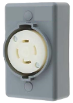
Figure 452
- The grounding plug is similar to the one shown (United States, Canada and Mexico only):
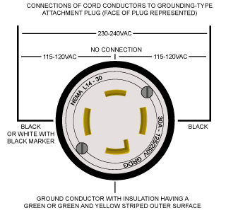
Figure 453
- Ensure that the equipment is connected to an outlet that matches the plug configuration.
- The equipment must not be connected to any different type of electric circuit.
- No adapter is available, or should be used with this equipment.
- For countries other than United States, Canada and Mexico; OMAX does not supply a suitably rated industrial grade plug.
- Contact a qualified electrician or service personnel for installation of a suitably rated industrial grade plug in accordance with national, state, and local codes.
- A pin and sleeve plug, rated at least 30A, 230V, 2-pole+E (3-wire grounding), IP44 or better, having a first-make last-break protective bonding contact (earthing contact) in accordance to standards IEC 60309-1 and IEC60309-2 may fulfill this requirement.
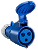
Figure 454
- You must plug the cord into a matching outlet that is properly installed and grounded in accordance with all local codes and ordinances.
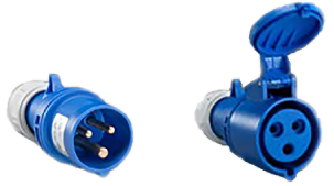
Figure 455
Explosive Atmosphere Precautions
Machining certain types of material such as titanium with a waterjet may produce sparks. Do not operate the equipment in an explosive atmosphere. Do not allow explosive or flammable vapors to accumulate in the area of the equipment.
Disposing of Waste Materials
Dispose of cutting wastes properly and in accordance with all local and federal regulations. The abrasive waterjet produces two types of waste: the water used for cutting and the solid material that accumulates in the catcher tank. Although the garnet abrasive itself is inert, the waste deposited from the material being cut may require special handling.
In abrasive waterjet cutting, garnet particles are accelerated with high-pressure water to strike the material creating a residue of abrasive grit and eroded particles from the cut material. Eventually, this residual sludge settles to the catcher tank bottom and accumulates until it must be removed for disposal. Depending upon the material makeup of this sludge, different disposal constraints will be imposed by the various local and federal regulations. For example, when cutting toxic materials, such as lead or radioactive metals, appropriate measures for the safe disposal of this type of contaminated water and sludge must be rigidly followed. Always consult with your local utilities company about sewage or water treatment requirements and proper sludge disposal procedures.
Adequate Shop Ventilation
Proper ventilation in your work area will assist in dissipating the accumulation of gas, vapor, and fumes. Your machine contains water that will evaporate depending on the ambient temperature in your shop and the temperature of the water in the tank itself. In order to reduce impact on other equipment in your shop, you should maintain adequate ventilation in your shop. Additionally some materials (especially aluminum particles) in water are known to produce hydrogen in water.
When you cut aluminum, the fine particles in the tank react with the water to generate hydrogen. Normally, hydrogen bubbles to the surface and escapes into the shop in harmless, low concentrations.
Take care that no ignition source (such as open flame or electrostatic discharge) is nearby the equipment.
Watch for hydrogen bubbles when machining aluminum. If you cut a lot of aluminum, you will create aluminum powder from the removed material. This powder will accumulate at the bottom of the tank along with your garnet. The aluminum then reacts with the water, releasing Hydrogen gas in the process. If you cut a lot of aluminum on a regular basis, then this is something to take into consideration.
Do not allow smoking near the machine. Take care that no ignition source (such as open flame or electrostatic discharge) is nearby the equipment. Do not store flammable materials near the equipment. Be especially careful when cutting materials that create sparks, such as titanium—these can ignite gases in the tank.
Equipment Safety Features
The abrasive waterjet provides several built-in safety features:
Overpressure Protection
During operation, pump pressure is monitored to prevent an overpressure condition. If the pump exceeds the factory set maximum pressure limit, the safety relief valve activates and shuts down the pump unit.
Electrical Protection
The equipment controller includes short circuit, overcurrent, and thermal protection for the pump motor.
Electrical Disconnect/Emergency Machine Off (EMO)
An electrical disconnect/emergency machine off (EMO) switch is used to remove the main AC electrical supply from the machine. To isolate the machine from its electrical supply, always unplug the main AC supply power cord from its electrical supply outlet.
Safety Lid
The lid of the equipment is designed with a safety interlock to prevent waterjet operation when the lid is open.
Safety Legend
The following safety signal word panels and paragraph notifications may appear throughout this and other documentation. Each provides safety issue identification and recommended actions to avoid the hazard. Be alert! Follow the recommended safety actions and precautions to prevent injury or damage to the equipment.
Indicates a hazardous situation which, if not avoided, could result in death or serious injury.
Indicates a hazardous situation which, if not avoided, could result in minor or moderate injury.
Used to address practices not related to physical injury—property damage only.
Used to provide supplementary information, emphasize a point or give a tip for easier operation.
Required Tools
The following table contains a list of tools with the appropriate sizes that are needed to maintain the ProtoMAX. Tools listed with part numbers are included with the ProtoMAX or are available for purchase. Contact technical support for more information.
Additional tools needed to operate and maintain this equipment are in the applicable equipment guides.
| Icon | Tool | Size(s) |
|---|---|---|
|
|
Safety glasses | |

|
Open-end wrench | 1/2 in, 5/8 in., 3/4 in., 13/16 in., 1 in., 10 mm, 17 mm, 19 mm |

|
Torque wrench | 15–102 in-lb (2–12 N·m), 50–75 ft-lb (68–102 N·m) |
|
|
Crowfoot | 5/8 in., 13/16 in., 1 in., 19 mm |

|
Allen wrench | 1.5 mm, 3 mm, 4 mm, 5 mm |

|
Bucket | 1 gal |

|
Funnel, wide mouth | |
|
|
Shop rags | |
|
|
Blue Goop® (P/N 302692) |
|
|
|
Acid brush | |

|
Synthetic grease, electrical insulating (P/N 203996) |
|
|
|
Stand-off tool (P/N 317876) |
|
|
|
Screwdriver, flat | #2 |

|
Filter wrench (P/N 208885) |
|
|
|
Grease, silicone (P/N 209100) |
0.5 oz |
|
|
Gloves, safety | |
|
|
Soft blow mallet | |
|
|
Scrub brush | |
|
|
Hex socket | 3 mm, 4 mm, 5 mm |
|
|
Anti-seize compound | |
|
|
Spray bottle | |
|
|
Gloves, latex | |
|
|
Grease syringe P/N 309325 (prefilled with 204248 grease, synthetic, molydisulfide, NLGI 1-1/2, jetlube) |
|
|
|
Grease gun (P/N 318411) |
|
|
|
Strainer | |
|
|
Hand shovel | |
|
|
Brush, long flexible handle | |
|
|
Seal removal tool (P/N 316852) |
|
|
|
Arctic grease (P/N 202335) |


Introduction
Always follow the safety instructions presented in the Safety section to prevent serious injury or death.
This guide provides information and instructions needed to maintain the abrasive waterjet system. Follow the recommended Maintenance Schedule to maintain the system. It is important to inspect parts for wear or damage and to replace them as needed.
Maintenance Schedule
The following maintenance activities and schedules are provided to aid in the development of a successful maintenance program. After any maintenance procedure, flush the high-pressure lines. Use the maintenance log to record all performed maintenance to ensure a clean and efficient abrasive waterjet system.
| Task | Frequency | Reference |
|---|---|---|
| Pump maintenance | ||
| Change the crankcase oil | After the first 50 hours of operation | Change the Crankcase Oil |
| Annually, at pump rebuild, or every 250 hours after the first oil change | ||
| Inspect the wet end | Periodically for evidence of leaking, contact technical support if leaking | Inspect the Pump Wet End |
| Inspect/replace the safety valve | When leaking | Correct Safety Valve Water Leaks
Replace the Safety Valve |
| Water filtration maintenance | ||
| Change the water filter | When the filter gauge approaches 25 psi or lower while the pump is running | Change the Water Filter Cartridge and O-Ring |
| Inspect the filter housing O-ring | Periodically, replace every two years or if leaking | Change the Water Filter Cartridge and O-Ring |
| Table maintenance | ||
| Wash away garnet abrasive accumulation from equipment | Daily and as often as required to maintain a clean working environment | Remove the Accumulated Garnet
Clean the Cutting Stage |
| Remove all garnet, sludge, and slugs from the tank bottom | Whenever garnet abrasive reaches the bottom of the garnet collection bins or when excessive water turbulence is noticed during cutting | Clean the Catcher Tank |
| Empty and clean the garnet bins | When the garnet bins are full or as garnet accumulates in the bins | Clean the Garnet Bins |
| Inspect and clean the lid | As needed to ensure visibility of the cutting stage | Clean the Lid |
| Inspect and clean the cable track | Periodically to prevent the build-up of garnet or other debris that would cause the cables or the track to wear | Clean the Cable Track |
| Clean the catcher tank filters and drains | As needed or when water flow is restricted, replace when worn, or water flow is restricted | Clean the Catcher Tank Filters and Drains |
| Clean the frame and side panels | As needed | Clean the Frame
Clean the Side Panels |
| Inspect and replace individual slats | Rotate monthly or more frequently if needed; replace when excessively scored and no longer stable | Rotate or Replace the Slats |
| High-pressure lines and components | Replace if damaged or if continued leaking occurs; do not try to repair | Maintain the High-Pressure Lines and Components |
| Lubricate the X- and Y-axis lead screws and linear rails |
Annually or if squeaking; inspect the lead screw for dirt or damage, inspect the linear rails for dirt or damage; clean and grease if need Note
Use Arctic Grease only. Do not use other greases. Other greases can affect system operation. |
Lubricate the Y-axis Lead Screw and Linear Rail Bearing Carriage
Lubricate the X-axis Lead Screw and Linear Rail Bearing Carriages |
| Replace the electrical enclosure air filters | Approximately once per month, or more frequently if required based on shop conditions to maintain adequate airflow or temperature | Change the Electrical Control Enclosure Air Filter |
| Nozzle maintenance | ||
| Inspect the abrasive tubing | Before use, replace as needed | Replace the Abrasive Tubing |
| Clean the jewel orifice assembly and nozzle body | Once a week to prevent mineral buildup | Clean the Orifice and Nozzle Body |
| Change the nozzle filter and inspect, clean and replace the inlet body O-ring | After approximately 40 cutting hours or more frequently if needed | Replace the Nozzle Filter |
| Rotate or replace the nozzle mixing tube | Rotate 90 degrees (one-quarter turn) every 8 hours of cutting to even out wear; replace as needed | Rotate or Replace the Mixing Tube |
| Inspect and replace the nozzle splash guard | As needed when cracked, torn, or damaged | Rotate or Replace the Mixing Tube |
| PC Controller maintenance | ||
| Clean the keyboard | Daily or as needed | Per PC manufacturer instructions |
| Clean the monitor screen | As needed for sharp viewing | Per PC manufacturer instruction |
| Restart the laptop | Daily | Per PC manufacturer instruction |
| Update the ProtoMAX software | When OMAX releases updates | Download from the ProtoMAX website |
| Other as specified in the PC User's Manual (provided by the manufacturer | PC manufacturer-recommended | Per PC manufacturer instruction |
Maintenance Log
| Run Hours | Maintenance Performed | Done By | Date |
|---|---|---|---|
Pump Maintenance
This section contains procedures for performing the recommended pump maintenance. See the Maintenance Schedule for the recommended frequency for this task.
Always wear safety glasses when performing maintenance on the machine.

Prepare the Pump for Maintenance
| 5. | Turn OFF the machine. |
![]()
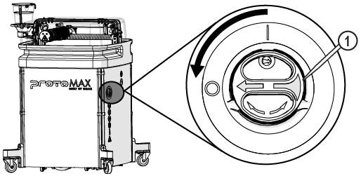
Figure 456
| 6. | Disconnect the power cord from the electrical outlet. |
| 7. | Turn OFF the water supply. |
| 8. | Ensure there is no pressurized water in the high-pressure lines. |
| a. | Open the lid and lock it in the upright position. |
Use care when opening or closing the lid to avoid injury. Never let the lid free-fall. Keep hand, fingers, or body parts away from the side of the table when closing the lid.
| b. | Loosen the gland nut [1] to release the pressure; water can leak from the inlet body weep hole. |


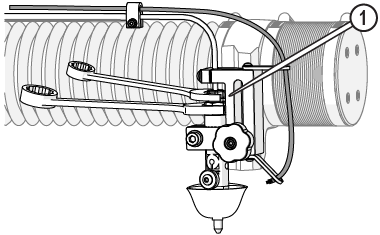
Figure 457
| c. | Tighten the gland nut [1]. |


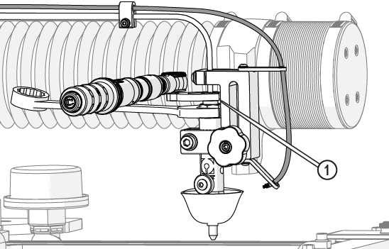
Figure 458
| 9. | Remove the side panels. |
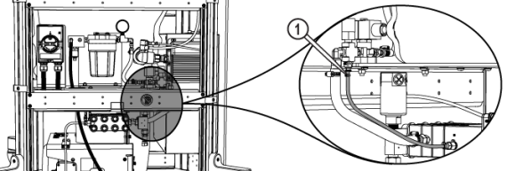
| 10. | Remove the front frame support bracket [1]. |

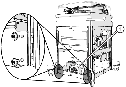
Figure 459
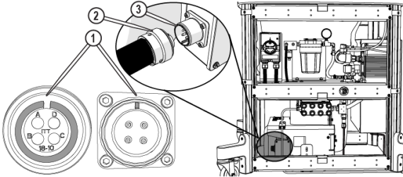
| 11. | Disconnect the pump power cable. |
![]()
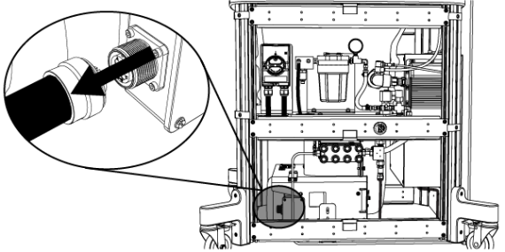
Figure 460
| 12. | Disconnect the high-pressure plumbing. |
Protect the connecting ends from external contamination or debris. Debris can enter into the high-pressure plumbing system and damage the pump or nozzle.

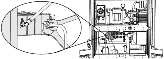
Figure 461
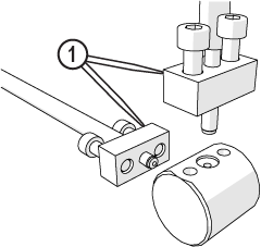
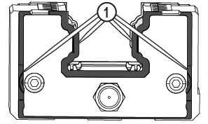
| 13. | Loosen the high-pressure support bracket [1] and remove the support cap [2]. |


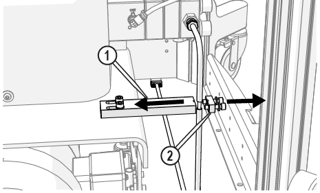
Figure 462
| 14. | Disconnect the cooling line OUT [1]. |
Protect the connecting ends from external contamination or debris. Debris can enter into the high-pressure plumbing system and damage the pump or nozzle.
![]()
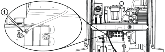
Figure 463
| 15. | Disconnect the cooling line IN [1]. |
Protect the connecting ends from external contamination or debris. Debris can enter into the high-pressure plumbing system and damage the pump or nozzle.
| 16. | Disconnect the incoming water hose [1]. |
Protect the connecting ends from external contamination or debris. Debris can enter into the high-pressure plumbing system and damage the pump or nozzle.
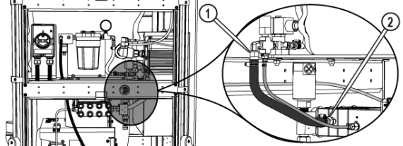
Figure 465
| 17. | Disconnect the transducer cable [1]. |
Protect the connecting ends from external contamination or debris. Debris can enter into the high-pressure plumbing system and damage the pump or nozzle.
![]()
![]()
Figure 466
| 18. | Unlock the pump wheels and move the pump out from the machine. |
Change the Crankcase Oil
Change the crankcase oil according to the intervals specified in the Maintenance Schedule to avoid excessive wear and damage to the crankcase bearings. The oil must also be changed anytime it becomes contaminated with water or other debris.
Recommended oil:
- Type: SAE 30 non-detergent (ISO 100)
- Amount: 40.6 ounces (1.2 liters)
- Operating condition: All operating temperatures
Using other types of oil can shorten pump life and void the warranty.
| 1. | Disconnect the pump, see the Prepare the Pump for Maintenance section. |
| 2. | Remove the pump cover. |
| a. | Remove the front screw [1] and set aside. |
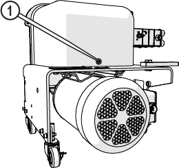
Figure 467
| b. | Loosen the captive screws [1] and remove the front crankcase cover. |
![]()
Figure 468
| 3. | Place a rag between the pump crankcase drain plug(Figure 469) and the frame [3] to catch oil drips. |
Crankcase oil can be hot. Be careful when removing the plug to prevent hot oil from flowing out and burning hands or fingers.
| 4. | Place a funnel and bucket below the crankcase drain plug(Figure 469). |
| 5. | Loosen or remove the oil filler port cap [2] (Figure 469). |

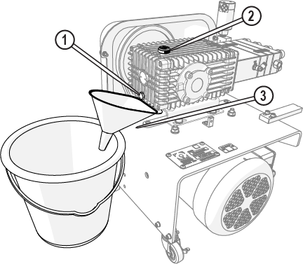
| 7. | Allow the oil to drain completely. |
Always dispose of used oil according to local environmental regulations.
| 8. | Replace the crankcase oil drain plug. |
| 9. | Fill with the correct amount of oil through the oil filler port. |
| 10. | Replace the oil filler port cap [2] (Figure 469). |
| 11. | Check the oil level, do one of the following. |
| • | Remove the dipstick [1] and make sure the oil level is at the full mark. |
| • | Make sure the oil level is at the top of the sight glass [2]. |
![]()
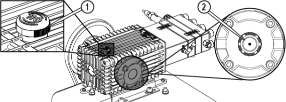
Figure 470
| 12. | Wipe any spilled oil from the crankcase and frame. |

| 13. | Replace the pump cover. |
| 14. | Reconnect the pump, see Place and Connect the Pump. |
| 15. | Reconnect the high-pressure plumbing, see Connect the High-Pressure Plumbing. |
| 16. | Reset the pump, see Reset the Pump. |
| 17. | Replace the side panels, see Install the Side Panels. |
Inspect the Pump Wet End
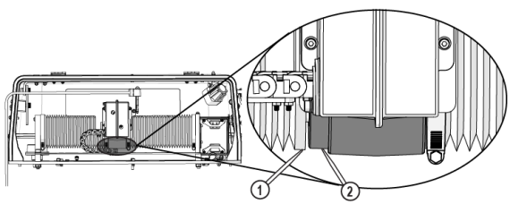
Inspect the pump between the crankcase [1] and the adapter block [2] for evidence of leaks. See the Maintenance Schedule for the recommended frequency for this task. If a leak is found, contact technical support.
![]()
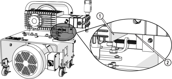
Figure 471
Correct Safety Valve Water Leaks
The following identifies the source of possible water leaks in the safety valve and how to correct them.
![]()
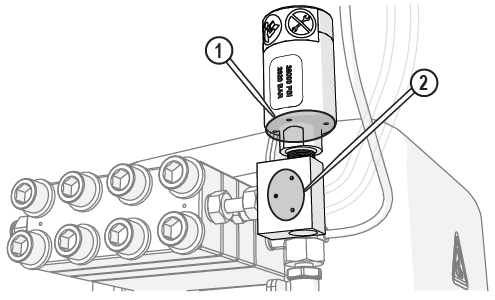
Figure 472
| Leak | Leak Description | Suspected Cause | Recommended Action |
|---|---|---|---|
| [1] | Leak from safety valve body weep holes | Seat to ceramic ball failure | Replace the Safety Valve |
| [2] | Leak from T-fitting weep holes | Seat failure | Replace the Safety Valve |
Replace the Safety Valve
Never attempt to adjust the safety valve; doing so creates a safety hazard and voids the warranty!
The safety valve functions to prevent excessive build-up of water pressure in the high-pressure plumbing system. During normal operation, the pump can reach extremely high pressures. When excessive-high pressures are detected, the variable frequency drive (VFD) slowly lowers the motor’s revolutions per minute (RPM) to prevent over-pressuring the system. If lowering the RPM does not prevent an overpressure condition, the safety valve activates when the factory preset pressure is reached (approximately 38 ksi), releasing the excess pressure.
Replacing the safety valve is required when leaking occurs during normal cutting operations.
If leaking continues to occur or if the calibration seal [1] has been broken, tampered with, or damaged, replacement of the safety valve assembly is required.
![]()
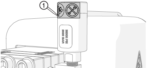
Figure 473
| 1. | Turn OFF the machine. |
![]()
Figure 474
| 2. | Remove the front and right side panels. |
| 3. | Disconnect the pump power cable. |
![]()
Figure 475
| 4. | Ensure there is no pressurized water in the high-pressure lines. |
| a. | Open the lid and lock it in the upright position. |
Use care when opening or closing the lid to avoid injury. Never let the lid free-fall. Keep hand, fingers, or body parts away from the side of the table when closing the lid.
| b. | Loosen the gland nut [1] to release the pressure; water can leak from the inlet body weep hole. |
Figure 476
| c. | Tighten the gland nut [1]. |
Figure 477
| 5. | Disconnect the transducer cable [1]. |
Protect the connecting ends from external contamination or debris. Debris can enter into the high-pressure plumbing system and damage the pump or nozzle.
![]()
![]()
Figure 478
| 6. | Loosen the T-fitting gland nut. |

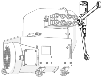
Figure 479
| 7. | Rotate the safety valve assembly counterclockwise until it contacts the water hose and can rotate no more. |
Safety valve internal components are loose and can fall out if the safety valve is removed while positioned vertically. Rotating the safety valve assembly to a more horizontal position before removal makes it more difficult for internal components to fall out on their own.
| 8. | Remove the safety valve [1]. |
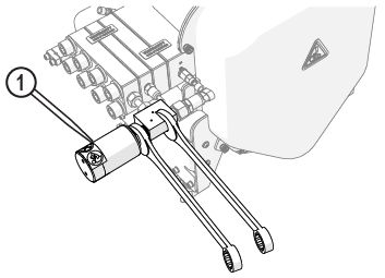
Figure 480
| 9. | Carefully remove the protective cap from the new safety valve. |
The protective cap keeps debris from contaminating the safety valve interior and keeps the internal components [1] from falling out. Always hold the safety valve with the stem up when removing the protective cap to keep the internal components from falling out and becoming contaminated with debris.
![]()
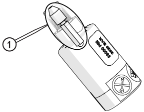
Figure 481
Avoid areas where Blue Goop can enter into the high-pressure water system (the tip of the safety valve body and the tip of the seat). Do not apply excessive amounts of Blue Goop onto the threads or seat of the safety valve. Excess Blue Goop can enter into the high-pressure water system and cause damage.
| 10. | Apply a very light coat of Blue Goop onto the coned end of the seat [1] and the threads [2] of the safety valve, if not already applied. |


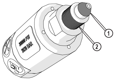
Figure 482
| 11. | Install the safety valve [1] onto the T-fitting [2] then hand-tighten. |
![]()
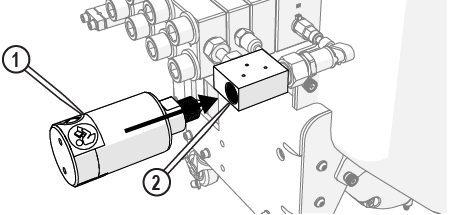
Figure 483
The jaws of the crowfoot must maintain a 90-degree angle to the horizontal axis of the torque-wrench handle throughout the torquing rotation. Other angles of orientation can alter the set torque.
![]()
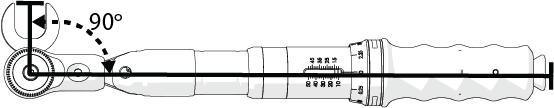
Figure 484
| 12. | Torque the safety valve [1]. |


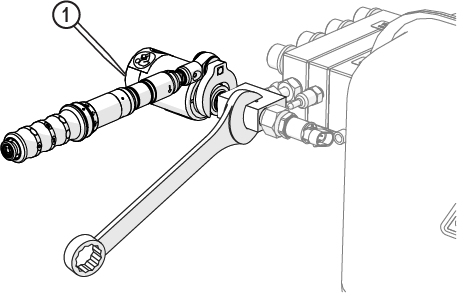
Figure 485
| 13. | Rotate the safety valve so that it is perpendicular to the floor. |
| 14. | Torque the T-fitting gland nut. |

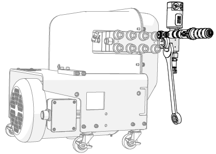
Figure 486
| 15. | Apply a heavy coat of dielectric compound to the transducer cable [2], then connect the transducer cable to the transducer [1]. |
![]()
Figure 487
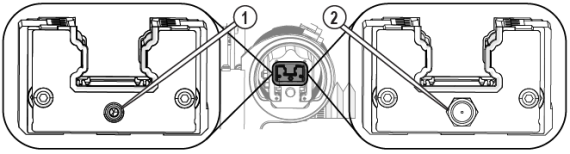
| 16. | Apply a heavy coat of dielectric compound to the power cord plug [2] (Figure 488). |
| 17. | Aline the notches [1] on the power cord plug and power connector [3], then push until the power cord plug seats in the power connector(Figure 488). |
| 18. | Rotate the shell counterclockwise until the threads engage, then turn the shell clockwise to tighten. |
| 19. | Flush the high-pressure plumbing, see Flush the High-Pressure Plumbing. |
| 20. | Reset the pump, see Reset the Pump. |
| 21. | Install the nozzle, if removed, see Install the Nozzle, perform a nozzle test, and see Test the Nozzle. |
| 22. | With the pump running at high pressure, carefully inspect the safety valve for signs of water leakage. Correct all leakage problems before continuing. |
| 23. | Replace the side panels, see Install the Side Panels. |
Place and Connect the Pump
| 1. | Roll the pump under the table, leaving a 1–2 in. space [2] between the back of the pump and the control cabinet, then lock one of the pump wheels [1]. |
![]()
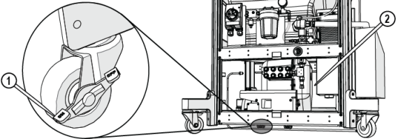
Figure 489
| 2. | Connect the cooling line OUT to the push-to-connect OUT connection [1] on the pump. The cooling OUT line and connections have yellow cable ties attached. |
![]()
Figure 490
| 3. | Connect the cooling line from the IN connection [2] on the pump to the push-to-connect fitting [1]. The cooling IN line and connections have red cable ties attached. |
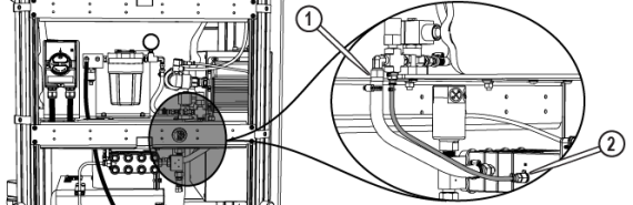
Figure 491
Do not use teflon tape or pipe sealant on the water connections. Teflon thread or sealant particles can enter into the high-pressure plumbing system and damage the pump and nozzle.
| 4. | Connect the supply water hose from the pump wet end [2] to the 90-degree fitting [1] and tighten. |
Figure 492
| 5. | Apply a heavy coat of dielectric compound to the transducer cable [2], then connect the transducer cable to the transducer [1]. |
![]()
Figure 493
| 6. | Apply a heavy coat of dielectric compound to the power cord plug [2] (Figure 488). |
| 7. | Aline the notches [1] on the power cord plug and power connector [3], then push until the power cord plug seats in the power connector(Figure 488). |
| 8. | Rotate the shell counterclockwise until the threads engage, then turn the shell clockwise to tighten. |
Connect the High-Pressure Plumbing
When preparing the ProtoMAX high-pressure tubing, it is critical to follow instructions. Some high-pressure tubing and fittings are pre-assembled. Fittings may need readjustment during installation to make sure proper seals and eliminate potential leaks. Use the provided Stand-off tool to make sure the fittings are correctly seated and sealed.
| 1. | Verify the u-shape high-pressure nipple, gland nut, slotted collet, and collar are assembled and aligned. See High-Pressure Gland Nut Assembly. |
High-pressure nipples have left-hand threads, therefore when connecting components, turn clockwise to loosen and counterclockwise tighten. Cross threading high-pressure connections can cause leaks or water damage from the leak(s).
| 2. | Verify the collar [1] is installed in the correct position using the stand-off tool [2], then adjust the collar to the correct depth if needed. |

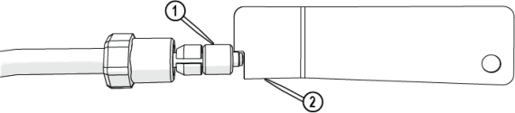
Figure 495
| 3. | Position the pump so that the high-pressure plumbing is aligned vertically and horizontally, and the rear of the pump is 1–2 in. from the control cabinet. |
![]()
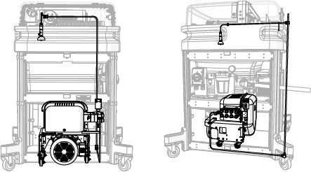
Figure 496
| 4. | Attach the assembled u-shape nipple [1] to the pump high-pressure outlet OUT connection [2] and hand-tighten. |
![]()

Figure 497
| 5. | Verify the gland nut [2] is set approximately to the depth of the nozzle stand-off tool [1]. |
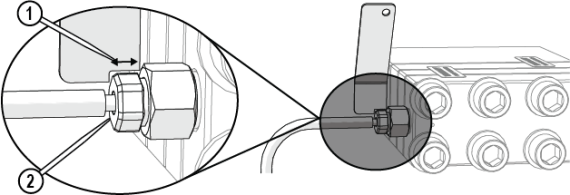
Figure 498
| 6. | Adjust the position of the bracket [1], then tighten the bracket. |
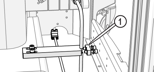
Figure 499
| 7. | Lock the pump wheels [1]. |
![]()
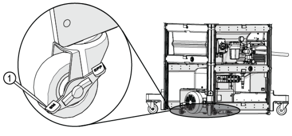
Figure 500
| 8. | Torque the pump connection (Figure 502). |
The jaws of the crowfoot must maintain a 90-degree angle to the horizontal axis of the torque-wrench handle throughout the torquing rotation. Other angles of orientation can alter the set torque.
![]()
Figure 501
| 9. | Attach the bracket cap [1] and tighten. |
Move the conduit out of the way so that it is not trapped under the bracket.

Figure 503
| 10. | Reinstall the front support bracket [1] with the provided hardware. |
Figure 504
Reset the Pump
The reset pump test runs a 30-second sequence to reset the pump. Do this test:
- Before operating the ProtoMAX for the first time
- After changing the nozzle orifice
- Repairing or replacing the pump
- Repairing high-pressure plumbing leaks
- When required by a fault or alert message
| 1. | Open MAKE. |
| 2. | Move the nozzle between two slats. |
| 3. | Click Test. |
| 4. | In Test Operations, select Reset Pump, and click Next. |
| 5. | Click Start Test and check the high-pressure plumbing for leaks (the dialog box closes when the test is complete). |
Table Maintenance
This section contains procedures for performing the recommended table maintenance. See the Maintenance Schedule for the recommended frequency for this task.
Always wear safety glasses when performing maintenance on the machine.
Change the Electrical Control Enclosure Air Filters
The air filters make sure debris and other pollutants do not enter the electrical enclosure. Regular air filter changes reduce wear and damage to enclosure control electronics. See the Maintenance Schedule for the recommended frequency for this task.
| 1. | Press up on the tabs located under the bottom edge [1] of the filter cover and lift the cover using both hands to unhinge it from the frame. |

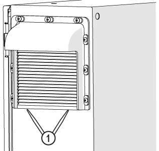
Figure 505
| 2. | Tilt and lift the filter cover out from the electrical control enclosure. |
| 3. | Remove and discard the old filter [1]. |
![]()
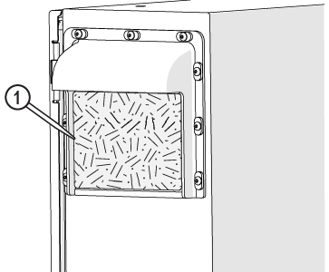
Figure 506
| 4. | Wipe any debris from the filter cover surfaces. |
| 5. | Press the new filter into the receptacle. |
| 6. | Reinstall the filter cover. |
| 7. | Repeat the steps to change the filter on the other side of the machine. |
Change the Water Filter Cartridge and Inspect O-ring
The water filter removes debris from the incoming water. See the Maintenance Schedule for the recommended frequency for this task.
| 1. | Turn OFF the machine. |
![]()
Figure 507
| 2. | Disconnect the power cord from the electrical outlet. |
| 3. | Turn OFF the water supply. |
| 4. | Ensure there is no pressurized water in the high-pressure lines. |
| a. | Open the lid and lock it in the upright position. |
Use care when opening or closing the lid to avoid injury. Never let the lid free-fall. Keep hand, fingers, or body parts away from the side of the table when closing the lid.
| b. | Loosen the gland nut [1] to release the pressure; water can leak from the inlet body weep hole. |
Figure 508
| c. | Tighten the gland nut [1]. |
Figure 509
| 5. | Remove the water filter housing [1]. |
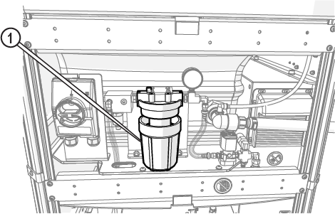
Figure 510
| 6. | Remove and discard the filter element. |
| 7. | Wash and rinse the filter housing to remove all sediment and coatings from inside the filter housing. |
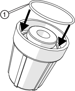
| 8. | Inspect the filter housing O-ring [1] for damage and replace it if needed (Figure 511). |
| 9. | Apply a light coat of silicone to the filter housing O-ring [1], then insert it into the water filter housing. |
To prevent leaking, do not twist or bind the O-ring.
| 10. | Place the new filter element [1] into the filter housing [2]. |
The filter element is bi-directional and can be installed in either direction.
![]()
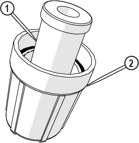
Figure 512
| 11. | Install the lower filter housing assembly to the upper filter housing and hand-tighten. |
Do not tighten the filter housing with the water filter wrench. Damage to the filter housing or filter housing O-ring can occur and can cause leaks.
| 12. | Turn ON the water supply. |
| 13. | Place a rag over the top of the filter, then hold down the air bleed button [1] to release air from the filter. |
If all of the air is not purged from the filter, the pump cannot develop sufficient pressure, and the pump shuts down.
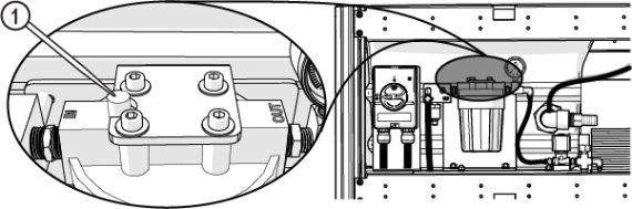
Figure 513
| 14. | Reset the pump to recalibrate the pump pressure. |
| 15. | Verify the water pressure when the pump is running. |
Rotate or Replace the Slats
Bacteria in the tank water can build up. A minor break in the skin can introduce harmful bacteria into a wound. Always wear protective gloves if you have cuts or open wounds on your hands. Wear gloves that protect against sharp metal edges.
In time, table slats can become scored with deep garnet abrasive waterjet cuts and become unable to provide stability and support required for precision cutting. See the Maintenance Schedule for the recommended frequency for this task.
The working life of a slat can be significantly improved by periodically rotating them to different table locations.
When replacing a defective slat, inspect the slat comb for excessive wear and replaced them as needed. Worn slat combs allow the slats to rock back and forth, which can interfere with cutting precision.
| 1. | Open the lid and lock it in the upright position. |
Use care when opening or closing the lid to avoid injury. Never let the lid free-fall. Keep hand, fingers, or body parts away from the side of the table when closing the lid.
| 2. | Remove the garnet bins. |
![]()
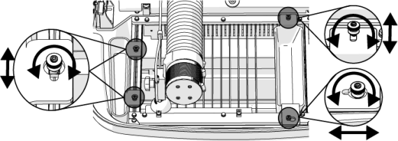
Figure 514
| 3. | Loosen the cutting deck bolts [1] and align the t-nuts [2] with the frame slot [3]. |

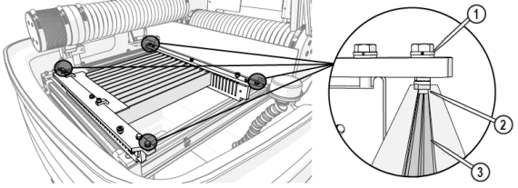
Figure 515
| 4. | Move the Y-axis to allow enough space to remove the cutting deck. |
Use care when removing the cutting deck to avoid damage to the Y- and Z-axes and the nozzle assembly.
| 5. | Carefully lift the cutting deck out of the catcher tank. |
![]()
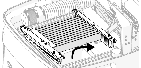
Figure 516
| 6. | Place a mark on the mounting plate of the fixturing plate location. |
If a mark is not placed on the mounting plate, a new fixturing plate needs to be cut after re-installation.
![]()
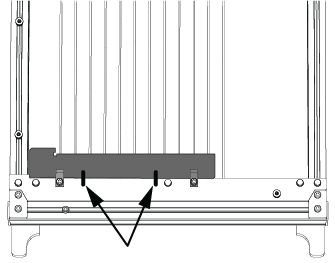
Figure 517
| 7. | Loosen the fixturing plate screws [1] and remove the fixturing square [2]. |
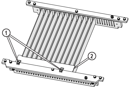
Figure 518
| 8. | Remove the screws [1] and the mounting plates [2]. |
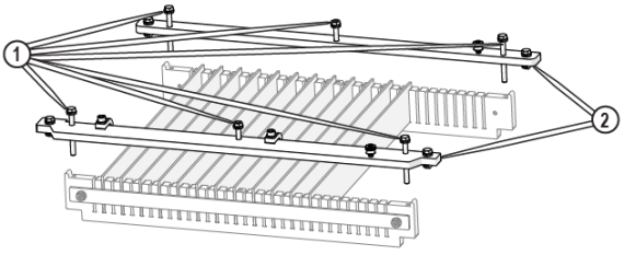
Figure 519
| 9. | Reinstall the screws [1] in the slat combs and hand-tighten to prevent dirt or debris from entering the screw threads. |
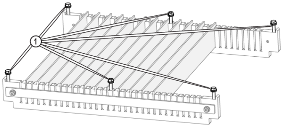
| 10. | Remove all badly worn slats. |
| 11. | Tap the slat combs and slats with a soft blow mallet to dislodge encrusted garnet, if needed. |

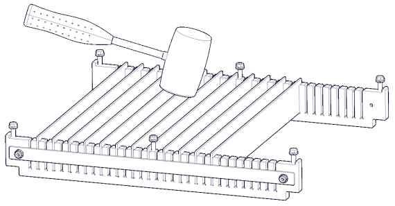
Figure 521
| 12. | Clean the slat combs and spray the slat assembly with a strong stream of water. |

| 13. | Rotate or replace slats as needed. |
Ensure the slat(s) [1] are seated flat against the slat comb slot [2]. Slightly raised slats can cause materials to wobble while cutting.
![]()
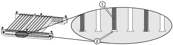
Figure 522
| 14. | Remove the screws and t-nuts from the mounting plate. |
| 15. | Apply a coat of anti-seize to the threads of the mounting plate screws and t-nuts. |

| 16. | Reinstall the mounting plates [2]. |
| 17. | Clean the frame t-slot [1], spray with a strong stream of water if needed. |
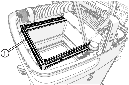
Figure 524
| 18. | Reinstall the cutting deck. |
Use care when installing the cutting deck to avoid damage to the Y- and Z-axes and the nozzle assembly.
| a. | Rotate the t-nuts to align with the frame slot and tighten the t-nut bolt. |
| b. | Place the cutting deck on the frame with t-nuts [1] in the frame slot [2]. |
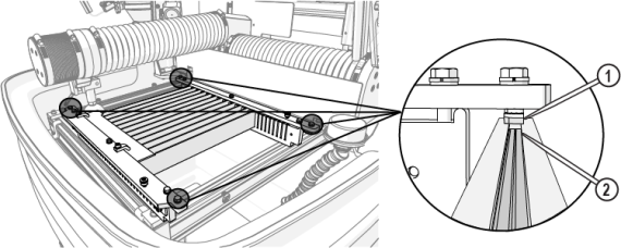
Figure 525
| c. | Make sure that the notches in the cutting deck align with the front mounting plate brackets. |
![]()
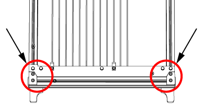
Figure 526
| d. | Loosen the t-nuts completely, then tighten to lock in place. |
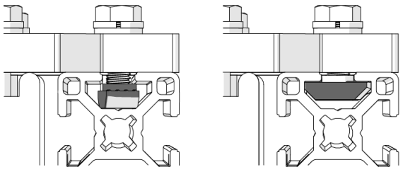
Figure 527
Figure 528
| 19. | Align the fixturing plate to the marks and tighten the screws [1] or recut the fixturing square [2]. See the Software Help files about fixturing squares. |
Figure 529
| 20. | Reinstall the garnet bins. |
![]()
Figure 530
Use care when opening or closing the lid to avoid injury. Never let the lid free-fall. Keep hand, fingers, or body parts away from the side of the table when closing the lid.
| 21. | Close the lid. |
Maintain the High-Pressure Lines and Components
Maintaining proper cone angles on the body and tube is critical in creating a high-pressure seal. The seal is created when the angled metal edges of the tube cone seat press against the metal edges inside the body cone. The body cone inside has a slightly larger angle of the high-pressure fitting. This slight difference in angles between the body and tube cones creates a tight, metal-to-metal seal between both components. See 401542, Diagram, Exploded, HP System Components, ProtoMAX for part numbers. See the Maintenance Schedule for the recommended frequency for this task.
To avoid injury or damage, always make sure there is no high-pressure water in the lines, see Prepare the High-Pressure Lines for Repair before repairing high-pressure lines or components.
Prepare the High-Pressure Lines for Repair
Before performing maintenance on the high-pressure lines, release all pressurized water.
| 1. | Turn OFF the macine [1], if needed. |
![]()
Figure 531
| 2. | Clean all high-pressure lines and components thoroughly before disassembly to remove all abrasive and debris. |
| 3. | Turn OFF the water, if needed. |
| 4. | Turn OFF the breaker power switch, if needed. |
| 5. | Make sure there is no pressurized water in the high-pressure lines. |
| a. | Open the lid and lock it in the upright position. |
Use care when opening or closing the lid to avoid injury. Never let the lid free-fall. Keep hand, fingers, or body parts away from the side of the table when closing the lid.
| b. | Loosen the Z-axis tubing clamp [1]. |
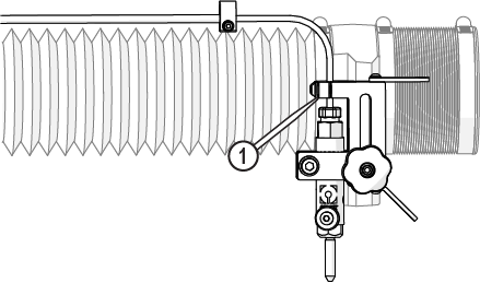
Figure 532
| c. | Loosen the gland nut [1] to release the pressure; water can leak from the inlet body weep hole. |
Figure 533
| d. | Tighten the gland nut [1], if needed. |
Figure 534
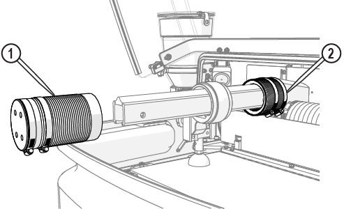
High-Pressure Gland Nut Assembly
Gland nut connections are located at the high-pressure nozzle and the pump. The high-pressure gland nuts consist of the following components.
![]()
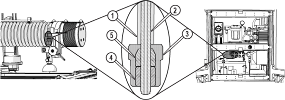
Figure 535
| [1] Conduit | [2] High-pressure nipple | [3] Gland nut | [4] Collar | [5] Slotted collet |
Maintain the Nozzle High-Pressure Gland Nut
When preparing the ProtoMAX high-pressure tubing, it is important to follow instructions. Some high-pressure tubing and fittings are pre-assembled. Fittings may need readjustment during installation to make proper seals and eliminate potential leaks. Use the provided stand-off tool to make sure the fittings are correctly seated and sealed.
Nipples contain small caps to protect the threading and keep debris from entering the high-pressure plumbing during shipment. Remove the caps before assembling the high-pressure plumbing fittings. Do not use pliers to remove the black caps or cut the black caps from the nipple. Pliers and knives damage the nipple threads causing leaks in the high-pressure lines and water damage.
| 1. | Release any pressurized water from the high-pressure lines, see Prepare the High-Pressure Lines for Repair. |
| 2. | Raise the Z-axis approximately 1 in. (3 cm). |
| 3. | Completely loosen the gland nut [1] from the inlet body. |
Figure 536
| 4. | If replacing the high-pressure line, loosen and remove the high-pressure fitting that is on the end of the high-pressure line that extends out from the back of the machine. See Maintain the High-pressure Fittings for removal instructions. |
| 5. | Loosen or remove the Z-axis tubing clamp [1]. |
Figure 537
| 6. | Replace the damaged component. |
If replacing the high-pressure nipple, remove the tubing clamp [1] and disassemble the fitting at the rear of the cutting deck, see Maintain the High-Pressure Fittings, remove the old nipple from the conduit, then insert the new nipple in the conduit and reattach the tubing clamp.


Figure 538
| 7. | Rotate the nipple cap clockwise to remove it and make sure that there is no debris in the high-pressure tube, if needed. |
![]()
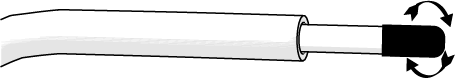
Figure 539
| 9. | Place the slotted collet [2] on the nipple with the tapered end facing the gland nut [1] (Figure 540). |
| 10. | Thread the collar [3] on to the nipple(Figure 540). |
| 11. | Use the stand-off tool [1] to set the collar depth. |
High-pressure nipples have left-hand threads, therefore when connecting components, turn clockwise to loosen and counterclockwise tighten. Cross threading high-pressure connections can cause leaks and water damage from the leak(s).
| 12. | Support the high-pressure tube [1], so the nipple is perpendicular [2] to the inlet body [3], then attach the gland nut to the inlet body and hand-tighten (Figure 540) |
![]()
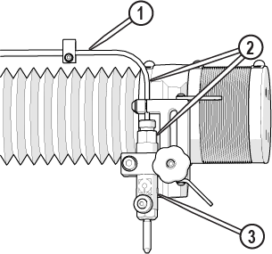
Figure 542
| 13. | Torque the gland nut [1]. |
Figure 543
| 14. | Attach the z-axis tubing clamp [1]. |
Figure 544
| 15. | Install and tighten the nipple tubing clamp [1]. |
Figure 545
| 16. | Flush the high-pressure plumbing, see Flush the High-Pressure Plumbing. |
| 17. | Reset the pump, see Reset the Pump. |
| 18. | Install the nozzle, if removed, see Install the Nozzle, perform a nozzle test, and see Test the Nozzle. |
Maintain the Pump High-Pressure Gland Nut
When preparing the ProtoMAX high-pressure tubing, it is important to follow instructions. Some high-pressure tubing and fittings are pre-assembled. Fittings may need readjustment during installation to make proper seals and eliminate potential leaks. Use the provided stand-off tool to make sure the fittings are correctly seated and sealed.
Nipples contain small caps to protect the threading and keep debris from entering the high-pressure plumbing during shipment. Remove the caps before assembling the high-pressure plumbing fittings. Do not use pliers to remove the black caps or cut the black caps from the nipple. Pliers and knives damage the nipple threads causing leaks in the high-pressure lines and water damage.
| 1. | Thoroughly clean all high-pressure components before disassembly. |
| 2. | Release any pressurized water from the high-pressure lines, see Prepare High-Pressure Lines for Repair. |
| 3. | Loosen the gland nut. |
Figure 546
| 4. | Remove the bracket cap [1]. |
Figure 547
| 5. | Replace the damaged component. |
If replacing the high-pressure nipple, disassemble the fitting at the rear of the machine, see Maintain the High-Pressure Fittings, then remove the old nipple from the conduit, then insert the new nipple in the conduit.
| 6. | Rotate the nipple cap clockwise to remove it and verify there is no debris in the high-pressure tube. |
![]()
Figure 548
| 7. | Place the gland nut [1] on the nipple. |
![]()
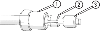
Figure 549
| 8. | Place the slotted collet [2] on the nipple with the tapered end facing the gland nut [1] and thread the collar [3] on the nipple (Figure 95). |
| 9. | Use the stand-off tool [1] to verify the collar depth. |
High-pressure nipples have left-hand threads, therefore when connecting components, turn clockwise to loosen and counterclockwise to tighten. Cross threading high-pressure connections cause leaks and water damage from the leak(s).
![]()
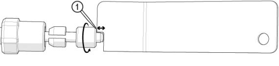
Figure 550
| 10. | Position the pump so that the high-pressure plumbing is aligned vertically and horizontally, and the rear of the pump is 1–2 in. (3–5 cm) from the control cabinet. |
![]()
Figure 551
| 11. | Attach the assembled u-shape nipple [1] to the pump high-pressure outlet OUT connection [2] and hand-tighten. |
![]()
Figure 552
| 12. | Verify the gland nut [2] is set approximately to the depth of the nozzle stand-off tool [1]. |
Figure 553
| 13. | Adjust the position of the bracket [1], then tighten the bracket. |
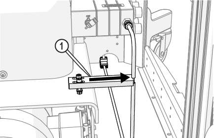
Figure 554
| 14. | Lock the pump wheels [1]. |
![]()
Figure 555
The jaws of the crowfoot must maintain a 90-degree angle to the horizontal axis of the torque-wrench handle throughout the torquing rotation. Other angles of orientation can alter the set torque.
![]()
Figure 556
| 15. | Torque the pump connection. |
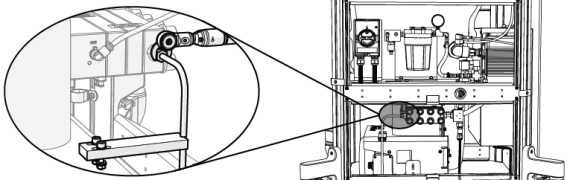
Figure 557
| 16. | Attach the bracket cap [1] and tighten. |
Move the conduit out of the way so that it is not trapped under the bracket.
Figure 558
| 17. | Flush the high-pressure plumbing, see Flush the High-Pressure Plumbing. |
| 18. | Reset the pump, see Reset the Pump. |
| 19. | Install the nozzle, if removed, see Install the Nozzle, perform a nozzle test, and see Test the Nozzle. |
Maintain the High-Pressure Fittings
Nipples contain small caps to protect the threading and keep debris from entering the high-pressure plumbing during shipment. Remove the caps before assembling the high-pressure plumbing fittings. Do not use pliers to remove the black caps or cut the black caps from the nipple. Pliers and knives can damage the nipple threads causing leaks and water damage.
When preparing the ProtoMAX high-pressure tubing, it is important to follow instructions. Some high-pressure tubing and fittings are pre-assembled. Fittings may need readjustment during installation to make sure proper seals and eliminate potential leaks. Use the provided stand-off tool to make sure the fittings are correctly seated and sealed.
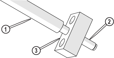
High-pressure fitting connections are located on the ends of the high-pressure nipple at the back of the machine. The high-pressure fittings consist of the following components.
![]()
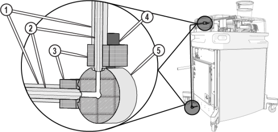
Figure 559
| [1] Conduit | [2] High-pressure nipple | [3] Bar clamp | [4] Bar clamp screw (x 2 per bar clamp) | [5] 90-degree fitting |
| 1. | Thoroughly clean all high-pressure components before disassembly. |
| 2. | Release any pressurized water from the high-pressure lines, see Prepare the High-Pressure Lines for Repair. |
Always loosen the high-pressure bar clamp screws evenly (1/4–1/2 turn at a time). Unevenly loosening the fitting can damage the tapered nipple or concave fitting and can cause leaks in the high-pressure fitting.
| 3. | Remove the bar clamp [1]. |
| 4. | Replace the component and reassemble high-pressure connections. |
If replacing the high-pressure nipple at the nozzle or pump, see High-Pressure Gland Nut Assembly.
| a. | Place the high-pressure line [2] in the conduit [1] (Figure 561). |
| 5. | Seat the high-pressure nipple [1] into the high-pressure fitting [2] and secure with the bar clamp and screws. |
![]()
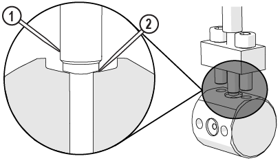
Figure 562
| 6. | Tighten the bar clamp screws [1] evenly. |
Always tighten the bar clamp screws evenly (1/4–1/2 turn at a time) to the correct torque to make sure the high-pressure nipple seats correctly. Do not overtighten the bar clamp screws. Over tightening the screws can damage the high-pressure nipple tapered edge or the concave high-pressure fitting and damage the high-pressure seal. Damaged high-pressure seals can cause the connection to leak.


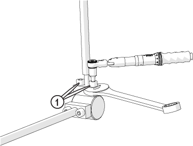
Figure 563
There is a small, even space [1] between the bar clamp and the high-pressure fitting when correctly torqued.
![]()
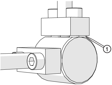
Figure 564
| 7. | Flush the high-pressure plumbing, see Flush the High-Pressure Plumbing. |
| 8. | Reset the pump, see Reset the Pump. |
| 9. | Install the nozzle, if removed, see Install the Nozzle, perform a nozzle test, and see Test the Nozzle. |
Lubricate the Lead Screws and Linear Rails
The X- and Y- axes lead screws should be lubricated periodically to make sure smooth and quiet operation. The X-and Y-axes linear rails should be inspected, cleaned, and lubricated periodically. See the Maintenance Schedule for the recommended frequency for this task.
Use Arctic Grease only. Do not use other greases. Other greases can affect system operation.
Lubricate the Y-Axis Lead Screw and Linear Rail Bearing Carriage
| 1. | Open the lid and lock it in the upright position. |
Use care when opening or closing the lid to avoid injury. Never let the lid free-fall. Keep hand, fingers, or body parts away from the side of the table when closing the lid.
| 2. | Move the Z-axis to the middle of the cutting deck. |
| 3. | Turn OFF the machine and close MAKE. |
To avoid damage, do not use flammable liquids or other chemicals to clean the equipment.
| 4. | Rinse and wipe away all debris from the bellows [1]. |

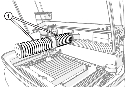
Figure 565
| 5. | Place a piece of cardboard on the cutting deck to keep components or tools from falling in the catcher tank. |
| 6. | Loosen the center clamps [1]. |
Do not move the bellows away from the Y-axis carriage. The area around the Y-carriage must be clean of debris to prevent erosion damage to the internal components.
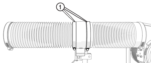
Figure 566
| 7. | Push up on the bottom of the clamps [1] to loosen, then slide the clamps toward the ends. |
Clamps can stick to the bellows. To prevent damage to the bellows, use care when removing the clamps.
![]()
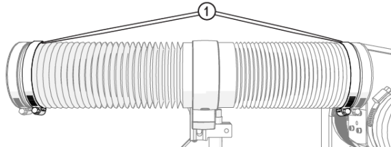
Figure 567
| 8. | Wipe the bellows ends [1] and Y-axis carriage with a clean rag; remove all debris. |
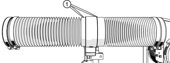
Figure 568
| 9. | Remove the end capscrews [1] and set aside. |
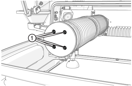
Figure 569
Use care when removing the bellows from the Y-axis carriage. Ripping or tearing of the bellows ends can allow debris in the Y-axis and can cause damage to the internal components.
| 11. | Slide the rear bellows [2] from the Y-axis carriage(Figure 570). |
| 12. | Clean all debris from around the lead screw nut [1] with a dry, soft cloth. |
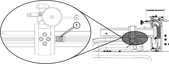
Figure 571
| 13. | Apply a light coat of lubricant, approximately a 1/8 in. bead, along the length of the lead screw [1]. |


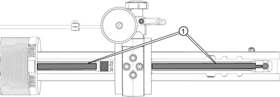
Figure 572
| 14. | Turn ON the machine and open MAKE. |
| 15. | Using MAKE, move the Y-axis the full length of travel three times. |
![]()
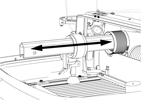
Figure 573
| 16. | Wipe off any excess lubricant. |
| 17. | Close MAKE and turn OFF the machine. |
Rotating the bellows helps to eliminate rub marks or holes on the interior of the bellows, prolongs the bellows life. If needed, loosen the clamp at both ends of the bellows, rotate the bellows approximately 90 degrees then secure with the clamps.
| 18. | Reattach the rear bellows to the Y-axis carriage, pulling the bellows lip over the Y-axis carriage edge. |
Ensure there is an even gap [1] between the Y-axis carriage housing and the bellows lip to keep debris from entering into the bellows and causing damage to the interior components.
![]()
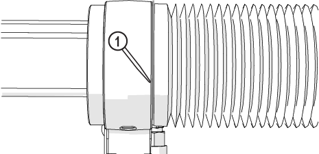
Figure 574
| 19. | Secure the bellows with the clamp [1]. |
Make sure the bellows cuff does not move away or come off while tightening the clamp.
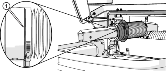
Figure 575
| 20. | Turn ON the machine, move the Z-axis forward until it reaches the hard stop. |
| 21. | Turn OFF the machine. |
![]()
Figure 576
| 22. | Identify if the lead screw support bracket configuration, then complete the applicable procedure. |
| • | If there is access [1] to the grease port, go to Lubricate the Y-Axis Linear Rail Bearing Carriage with Grease Port Access. |
![]()
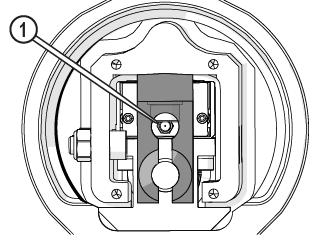
Figure 577
| • | If there is no access [1] to the grease port, go to Lubricate the Y-Axis Linear Rail Bearing Carriage without Grease Port Access. |
![]()
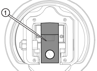
Figure 578
Lubricate the Y-Axis Linear Rail Bearing Carriage with Grease Port Access
Use Arctic Grease only. Do not use other greases. Other greases can affect system operation.
| 1. | Attach the grease gun nipple to the grease fitting [1]. |

Figure 579
Do not apply excessive grease to the linear rail bearing carriage. Pumping excessive amounts of grease into the carriage can displace the carriage lip seal [1].
![]()
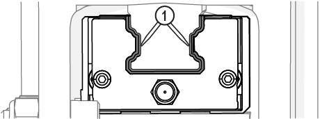
Figure 580
| 2. | Pump grease into the linear rail bearing carriage until grease appears at any location along the edge of the carriage [1]. |
| 3. | Attach the Y-axis end cap and bellows, see Attach the Y-Axis End Cap and Bellows. |
Lubricate the Y-Axis Linear Rail Bearing Carriage without Grease Port Access
Use Arctic Grease only. Do not use other greases. Other greases can affect system operation.
| 1. | Remove the lead screw support bracket [1]. |
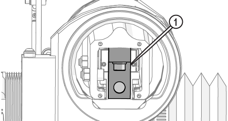
Figure 582
| 2. | Identify if the linear rail bearing carriage has a set screw [1] or grease fitting [2]. |
If there is a grease fitting, complete Step 3. If there is a set screw, complete Step 4.
| 3. | Lubricate linear rail bearing carriage with a grease fitting. |
| a. | Attach the grease gun nipple to the grease fitting. |
Do not apply excessive grease to the linear rail bearing carriage. Pumping excessive amounts of grease into the carriage can displace the carriage lip seal [1].
![]()
Figure 584
| b. | Pump grease into the linear rail bearing carriage until grease appears at any location along the edge of the carriage [1]. |
| 4. | Lubricate linear rail bearing carriage without a grease fitting: |
| a. | Remove the set screw [1]. |

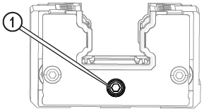
Figure 586
| b. | Insert the grease gun needle into the set screw port. |
| c. | Pump grease into the linear rail bearing carriage until grease appears at any location along the edge of the carriage [1] (Figure 581). |
To avoid damaging the linear rail bearing carriage, do not over tighten the set screw.
| d. | Replace the set screw and tighten it. |
| 5. | Move the Z-axis to the rear of the cutting deck. |
To prevent damage to the lead screw support bracket and other internal components, do not over tighten the lead screw support bracket.
| 6. | Install the lead screw support bracket [1], ensuring the end of the lead screw is secured in the support bracket. |


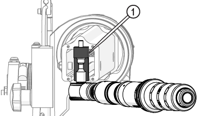
Figure 587
| 7. | Attach the Y-axis end cap and bellows, see Attach the Y-Axis End Cap and Bellows. |
Attach the Y-Axis End Cap and Bellows
| 1. | Using MAKE, move the Z-axis forward, approximately 5–6 inches from the front hardstop. |
| 2. | Reattach the end cap and bellows. |
Rotating the bellows helps to eliminate rub marks or holes on the interior of the bellows, prolongs the bellows life. If needed, loosen the clamp at both ends of the bellows, rotate the bellows approximately 90 degrees then secure with the clamps.
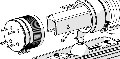
Figure 588
Figure 589
| 3. | Pull the front bellows to the Y-axis carriage, pulling the bellows lip over the y-axis carriage, ensuring there is an even gap all around the y-axis carriage. |
![]()
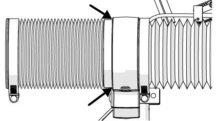
Figure 590
| 4. | Attach the clamp, confirm the gap around the Y-axis carriage then tighten the clamp. |
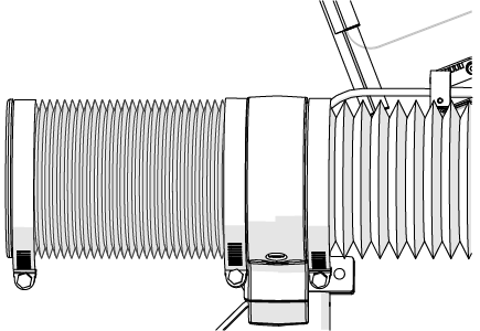
Figure 591
| 5. | Verify the bellows cuff [1] has not pulled away from the carriage housing. |
![]()
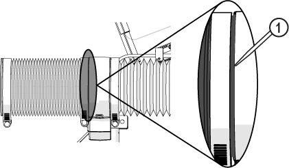
Figure 592
| 6. | Move the Y-axis forward and backward three full strokes to distribute the lubricant along the lead screw. |
![]()
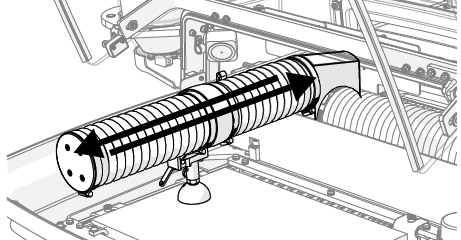
Figure 593
Lubricate the X-Axis Lead Screw and Linear Rail Bearing Carriages
Use Arctic Grease only. Do not use other greases. Other greases can affect system operation.
![]()
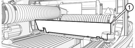
Figure 594
| 1. | Remove the bellows protector splash shield [1]. |
| 2. | Move the Y-axis to the middle of the cutting deck. |
| 3. | Turn OFF the machine, close MAKE, and close the front lid. |
| 4. | Remove the screws and washers [1] securing the rear lid and set aside. |
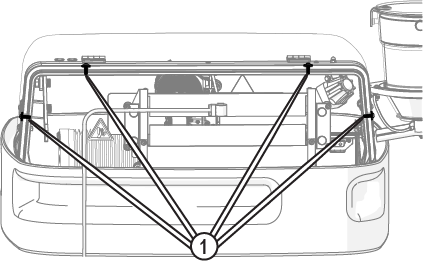
Figure 595
| 5. | Lift the lid, then slide it down the high-pressure plumbing to the floor. |
To prevent scratches to the lid, place it on a soft surface.
![]()
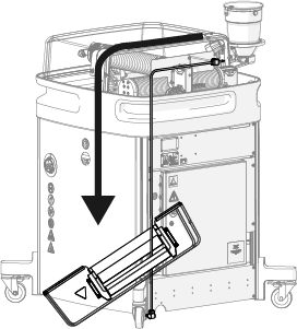
Figure 596
| 6. | Rinse and wipe away all debris from the bellows [1]. |
Figure 597
| 7. | Place a piece of cardboard on the cutting deck to keep components or tools from falling in the catcher tank. |
Do not move the bellows away from the X-axis carriage. The area around the X-carriage must be clean of debris to prevent erosion damage to the internal components.
| 8. | Loosen the center clamps [1]. |
Figure 598
Figure 599
| 9. | Push up on the bottom of the clamps to loosen, then slide the clamps toward the ends. |
| 10. | Wipe the bellows ends [1] and X-axis carriage with a clean rag; remove all debris. |
| 11. | Move the bellows to the ends of the axis and clean all debris from around the lead screw nut [1] with a dry, soft cloth. |
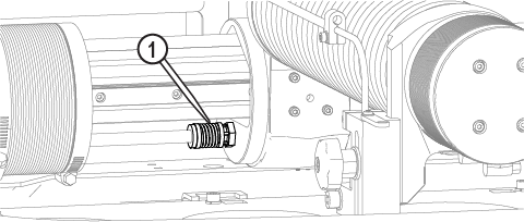
Figure 600
| 12. | Apply a light coat of lubricant, approximately 1/8 in. bead, along the length of the lead screw [1], then spread the lubricant along the lead screw surface. |
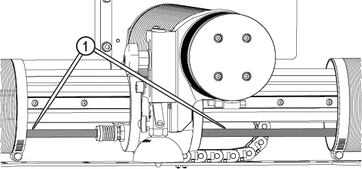
Figure 601
Figure 602
| 13. | Turn ON the machine, open MAKE, then move the X-axis to one side. |
| 14. | Identify if the linear rail bearing carriage has a set screw [1] or grease fitting [2], then complete the appropriate step. |
![]()
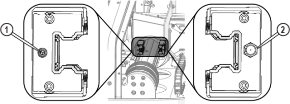
Figure 603
| 15. | Lubricate linear rail bearing carriages with a grease fitting: |
| a. | Attach the grease gun nipple to the grease fitting. |
| b. | Pump the grease into the linear rail bearing carriage until it comes out the edges [1]. |
| 16. | Lubricate linear rail bearing carriages without a grease fitting: |
| a. | Remove the set screw. |
| b. | Insert the grease gun needle into the set screw port. |
| c. | Pump the grease into the linear rail bearing carriage until it comes out the edges [1] (Figure 604). |
To avoid damaging the linear rail bearing carriage, do not over tighten the set screw.
| d. | Replace the set screw and tighten it. |
| 17. | Reattach the bellows to the X-axis carriage, pulling the bellows lip [1] over the carriage edge [2]. |
Rotating the bellows helps to eliminate rub marks or holes on the interior of the bellows, prolongs the bellows life. If needed, loosen the clamp at both ends of the bellows, rotate the bellows approximately 90 degrees then secure with the clamps.
Make sure there is an even gap [1] between the X-axis carriage housing and the bellows lip to keep debris from entering into the bellows and causing damage to the interior components.
![]()
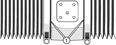
Figure 606
| 18. | Secure with the clamp. |
| 19. | Replace the bellows protector splash shield [1]. |
![]()
Figure 607
If needed, clean the cable track area before replacing the rear lid. See Clean the Cable Track.
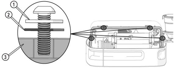
| 20. | Replace the rear lid and secure with the screws and washers (x 4) (Figure 608). |
To prevent damage to the lid [3], place the rubber washer [2] between the lid and the metal washer [1]. Do not over tighten the screw.

| 21. | Move the X-axis side to side three full strokes to distribute the lubricant along the lead screw. |
![]()
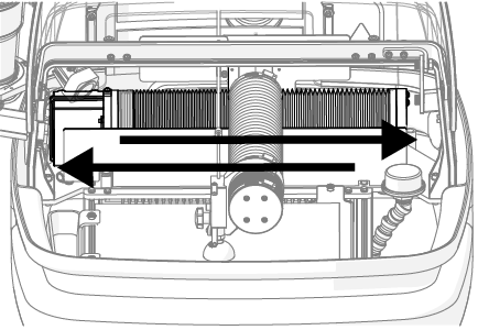
Figure 609
Use care when opening or closing the lid to avoid injury. Never let the lid free-fall. Keep hand, fingers, or body parts away from the side of the table when closing the lid.
| 22. | Close the lid. |
Clean the ProtoMAX
Do not use chemicals when cleaning the machine unless specified in the instructions. Chemicals can damage the machine or interfere with operation.
Keeping the ProtoMAX equipment clean and maintained is essential for long-term operation. Use care when cleaning the equipment because the particles used in abrasive waterjet machining are abrasive. The following instructions focus on best practices for cleaning the machine. A basic cleaning step is included as part of the equipment shutdown checklist, but cleaning the cutting deck area is recommended after cutting a part.
Abrasive waterjet cutting, by its nature, is a messy process. When cutting parts, abrasive in the jet stream erodes the material that is being cut. All of the water and particles create a sludge that builds up in and around the cutting area. Additionally, the mist from the cutting process accumulates on the inside of the cutting deck enclosure. Using the nozzle splash guard is a best practice for helping to keep the machine clean.
Remove the Accumulated Garnet
Since garnet abrasive and metal particles continually accumulate in the tank, regularly scheduled removal of accumulated deposits is necessary. When removing garnet abrasive material from the bottom of the tank, it is best to completely drain the water from the tank before attempting to remove the garnet abrasive waste. The drier the garnet abrasive, the easier it is to remove.
Used garnet abrasive by itself is not toxic and can be taken to a dump site or disposed of normally. However, if any hazardous materials were cut, the garnet abrasive waste becomes subject to several environmental regulations. Contact the local officials for proper disposal methods.
Clean the Garnet Bins
The garnet bins capture some of the spent particles introduced into the catcher tank during the cutting process. Particles settle into these bins rather than accumulate in the catcher tank. See the Maintenance Schedule for the recommended frequency for this task.
To avoid damage, do not use flammable liquids or other chemicals to clean the equipment.
Use care when emptying the bins. To avoid damage to the bins, do not strike the bins against objects or use sharp instruments to remove garnet from the bins.
| 1. | Open the lid and lock it in the upright position. |
Use care when opening or closing the lid to avoid injury. Never let the lid free-fall. Keep hand, fingers, or body parts away from the side of the table when closing the lid.
| 2. | Lower the water in the catcher tank to below the thumbscrews. |
| 3. | Spray a strong stream of water on the thumbscrews to remove all debris. |
| 4. | Loosen the thumbscrews and remove the garnet bins. |
![]()
Figure 610
| 5. | Rinse the garnet bins until clean. |
| 6. | Replace the garnet bins and tighten the thumbscrew. |
| 7. | Close the lid. |
Clean the Lid
To avoid damage, do not use flammable liquids or other chemicals to clean the equipment.
The lid contains the steam, mist, and particles emitted while cutting. Cutting underwater and using the nozzle splash guard helps limit the amount of particle emission into the enclosure. Cleaning the lid after each cut is a best practice. See the Maintenance Schedule for the recommended frequency for this task.
![]()
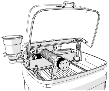
Figure 611
| 1. | Open the lid and lock it in the upright position. |
Use care when opening or closing the lid to avoid injury. Never let the lid free-fall. Keep hand, fingers, or body parts away from the side of the table when closing the lid.
| 2. | Gently spray the inside of the lid with water to rinse off accumulated abrasive and other particles. |
Garnet abrasive particles are like sand and can scratch the lid surface if wiped off.
| 3. | Gently wipe the inside and outside of the lid with a clean, soft cloth. |
| 4. | Close the lid. |
Clean the Cutting Stage
To avoid damage, do not use flammable liquids or other chemicals to clean the equipment.
The cutting stage is where all of the components to support and cut the material are located, including the cutting deck, the X, Y, and Z-axes, and the nozzle. See the Maintenance Schedule for the recommended frequency for this task.
| 1. | Open the lid and lock it in the upright position. |
Use care when opening or closing the lid to avoid injury. Never let the lid free-fall. Keep hand, fingers, or body parts away from the side of the table when closing the lid.
| 2. | Gently spray the X, Y, and Z-axes bellows [1] and components, the backplate [2], the cutting stage frame [3], material holding fixtures [4], and the slat or polymer cutting deck [5] to rinse the sludge into the catcher tank and garnet bins. |
To prevent water or sludge from splashing out of the machine, do not use a forceful spray of water.
![]()
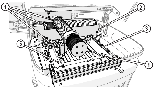
Figure 612
If cutting plastics or using the polymer cutting deck to support materials while cutting, plastic debris can accumulate on and around the cutting deck area. Excessive plastic debris can build up and clog the drain system.
| 3. | Remove the floating particles as they accumulate, using a strainer to skim the surface of the water. |

| 4. | Close the lid. |
Clean the Cable Track
To avoid damage, do not use flammable liquids or other chemicals to clean the equipment.
A cable track runs along the back of the machine behind the X-axis. The cable track protects the cables from crimping, binding, or other damage as they move along the X-axis of the machine. See the Maintenance Schedule for the recommended frequency for this task.
| 1. | Open the lid and lock it in the upright position. |
Use care when opening or closing the lid to avoid injury. Never let the lid free-fall. Keep hand, fingers, or body parts away from the side of the table when closing the lid.
| 2. | Gently spray with water to remove all particles from the cable track [1] and the surrounding area. |
![]()
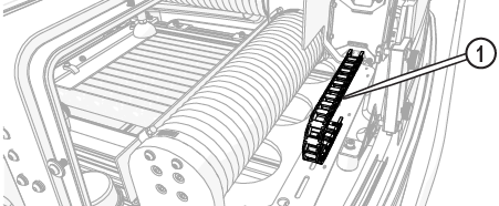
Figure 613
| 3. | Inspect the cable track for damage and if damaged, contact technical support. |
| 4. | Close the lid. |
Clean the Catcher Tank Filters and Drains
To avoid damage, do not use flammable liquids or other chemicals to clean the equipment.
The catcher tank has an adjustable drain and filter [1] and an overflow drain and filter [2] for maintaining the water level during operation. Each drain is equipped with a filter to keep garnet and other cutting debris in the catcher tank allowing the debris to accumulate in the garnet bins. See the Maintenance Schedule for the recommended frequency for this task.
![]()
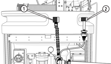
Figure 614
The machine is shipped with either metal screen filter [1] or a foam filter [2] installed. The metal screen filter screws onto the drainpipe, and the foam filter has a slot on the bottom for attaching to the drain pipe.
![]()
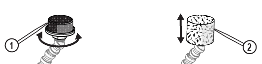
Figure 615
Water can damage the electrical control cabinet and other components. Always make sure the water in the catcher tank is removed, or the water is below the adjustable tank drain [1] and the tank overflow drain [2] before cleaning or removing the drain hoses and connections.
![]()
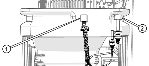
Figure 616
| 1. | Open the lid and lock it in the upright position. |
Use care when opening or closing the lid to avoid injury. Never let the lid free-fall. Keep hand, fingers, or body parts away from the side of the table when closing the lid.
| 2. | Remove the filters from the adjustable drain pipe and overflow drain. |
| 3. | Spray a strong stream of water through the adjustable pipe [1] and overflow tube [2] to wash away settled debris. |
If spraying the drain pipe and tube does not dislodge debris or the water flow remains restricted, the drain pipe and tubes may need to be removed and cleaned with a brush, see Remove Tank Drain Clog.
![]()
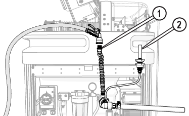
Figure 617
| 4. | Spray the filters with a strong stream of water to remove debris or replace if needed. |
| 5. | Reinstall the filters. |
| 6. | Close the lid. |
Clean the Catcher Tank
The catcher tank fills with sludge (spent abrasive garnet, material slugs, and other debris) during the cutting process and requires periodic cleaning. Clean the tank before or when the sludge reaches the bottom of the garnet bins or slats, when there is an increase of water turbulence while cutting, or before the flow is comprised. See the Maintenance Schedule for the recommended frequency for this task.
Bacteria in the tank water can build up. A minor break in the skin can introduce harmful bacteria into a wound. Always wear protective gloves if you have cuts or open wounds on your hands. Wear gloves that protect against sharp metal edges.
The garnet abrasive is not a chemical irritant, but if not quickly washed out, it can injure an eye just as sand would. Also, tank water could contain particles from the material or chemical irritants. Always wear eye protection when working on the ProtoMAX.
Spent garnet and catcher tank material can be heavy. Use care when lifting debris away from the machine to prevent injury.
To avoid damage, do not use flammable liquids or other chemicals to clean the equipment.
| 1. | Move the Y-axis and Z-axis out of the way. |
| 2. | Turn OFF the machine. |
![]()
Figure 618
| 3. | Open the lid and lock it in the upright position. |
Use care when opening or closing the lid to avoid injury. Never let the lid free-fall. Keep hand, fingers, or body parts away from the side of the table when closing the lid.
| 4. | Remove the water from the catcher tank. |
| 5. | Remove the garnet collection bins, clean, and set aside. |
![]()
Figure 619
| 6. | Remove the slat or polymer cutting deck for easy access. |
| a. | Loosen the cutting deck bolts [1] and align the t-nuts [2] with the frame slot [3]. |
Figure 620
| b. | Carefully lift the cutting deck out of the catcher tank. |
![]()
Figure 621
Use care when removing sludge from the catcher tank. Sharp objects can damage the catcher tank.
| 7. | Remove the sludge from the catcher tank bottom and place it in a bucket or other container for disposal (see Important Safety Information for Disposing of Waste Materials). |

| 8. | Inspect catcher tank armor plating for excessive damage (deep wear spots or holes, worn or thin edges and corners), replace if needed. |
| 9. | Reinstall the cutting deck. |
Figure 622
| 10. | Reinstall the garnet bins. |
![]()
Figure 623
| 11. | Fill the catcher tank with water. |
| 12. | Close the lid. |
Clean the Frame
Cleaning the frame keeps debris from corroding or damaging the machine. See the Maintenance Schedule for the recommended frequency for this task.
Never spray water into the frame or inside the frame area. Spraying water inside the frame can enter into the electrical control cabinet and cause damage to electrical components or create a shocking hazard.
To avoid damage, do not use flammable liquids or other chemicals to clean the equipment.
Wipe down the machine frame using a damp cloth or sponge.

Figure 624
Clean the Side Panels
To avoid damage, do not use flammable liquids or other chemicals to clean the equipment.
Keeping side panels in place when the machine is operating is essential in protecting internal components from water and other contaminants. See the Maintenance Schedule for the recommended frequency for this task.
Never spray water into the frame or inside the frame area. Spraying water inside the frame can enter into the electrical control cabinet and cause damage to electrical components or create a shocking hazard.
| 1. | Lightly spray the panels with a bottle filled with only water. |
| 2. | Gently wipe the panels with a damp, clean, soft cloth. |
Figure 625
Remove A Tank Drain Clog
The tank drain hose connects to the elbow that exits the catcher tank at the bottom right rear and runs to the drain. The tank overflow drain is a secondary tank drain that prevents water from overflowing out of the catcher tank if the primary drain, filter, or the flexible line becomes clogged. The secondary drain hose is attached and exits from behind the bottom of the catcher tank area. If rinsing the tank drains do not clear the blockage, then complete the following:
| 1. | Remove the water from the catcher tank. |
Sharp objects can damage the catcher tank. Use care when removing tank sediment to avoid damaging the catcher tank walls.
| 2. | Remove the sediment from the catcher tank. |
Remove a Flexible Tank Drain and Connection Clog
Water can damage the electrical control cabinet and other components. Always make sure the water in the catcher tank is removed, or the water is below the adjustable tank drain [1] and the tank overflow drain [2] before cleaning or removing the drain hoses and connections.
![]()
Figure 626
The tank drain pipe is attached to the drain filter and runs down to a drain elbow located in the bottom right, rear corner of the catcher tank. Silt and suspended particles from the cutting process can accumulate in this drain pipe and elbow over time, reducing the ability of the catcher tank water to drain from the tank. If the water flow from the catcher tank is compromised, clean the components of the drain.
![]()
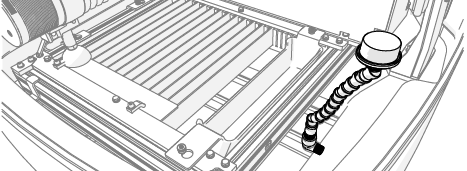
Figure 627
| 1. | Open the lid and lock it in the upright position. |
Use care when opening or closing the lid to avoid injury. Never let the lid free-fall. Keep hand, fingers, or body parts away from the side of the table when closing the lid.
| 2. | Remove the filter [1]. |
![]()
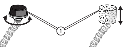
Figure 628
| 4. | Spray a strong stream of water through the drain pipe and elbow to rinse any debris or sludge from inside the components. |
| 5. | Scrub inside the flexible pipe and elbow to dislodge any remaining debris or sludge. |

| 6. | Clean the outside of the flexible pipe and rinse. |
| 7. | Replace the flexible pipe when joints are damaged or loose. |
Do not overtighten the flexible pipe connection. Over tightening can cause cracking and breaking of the flexible pipe or elbow connection and can cause leaks.
| 8. | Reattach the flexible pipe [1] to the elbow and tighten. |
![]()
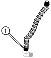
Figure 630
| 9. | Reinstall the drain filter [1]. |
![]()
Figure 631
| 10. | Close the lid. |
Remove an Overflow Drain Hose and Connection Clog
Water can damage the electrical control cabinet and other components. Always make sure the water in the catcher tank is removed, or the water is below the adjustable tank drain [1] and the tank overflow drain [2] before cleaning or removing the drain hoses and connections.
![]()
Figure 632
| 1. | Open the lid and lock it in the upright position. |
Use care when opening or closing the lid to avoid injury. Never let the lid free-fall. Keep hand, fingers, or body parts away from the side of the table when closing the lid.
| 2. | Remove the overflow drain hose from the -push-to-connect fittings at the drain elbow [1] and overflow port [2]. |
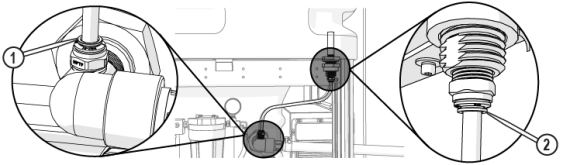
| 3. | Spray out the drain hose using a strong stream of water. |
To avoid damage, do not use flammable liquids or other chemicals to clean the equipment.
| 4. | Inspect and remove all debris from the drain ports. |
| 5. | Inspect the hose ends for damage. If damaged, replace the hose. |
Do not cut the hose; it is precut for optimal performance. Cutting the hose can cause leaking after filling the tank.
| 6. | Reinstall the overflow drain hose to the push-to-connect fittings at the overflow port [2] and drain elbow [1] (Figure 633). |
| 7. | Close the lid. |
Remove a Drain Hose and Connection Clog
Water can damage the electrical control cabinet and other components. Always make sure the water in the catcher tank is removed, or the water is below the adjustable tank drain [1] and the tank overflow drain [2] before cleaning or removing the drain hoses and connections.
![]()
Figure 634
| 1. | Cover the solenoid and pressure switch with plastic. |
| 2. | Remove the drain hose [1] from the drain elbow [2]. |
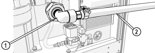
Figure 635
| 3. | Spray out the drain hose using a strong stream of water. |
To avoid damage, do not use flammable liquids or other chemicals to clean the equipment.
| 4. | Clean out built-up debris in the drain connection. |
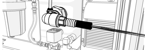
Figure 636
| 5. | Reinstall the drain hose [1] and secure it with the hose clamp [2]. |
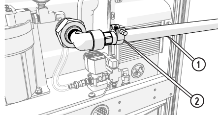
Figure 637
Install the Side Panels
| 1. | Slide one end of the panel into the support leg slot. |
Ensure the garnet abrasive inlet [2] points towards the front of the table. Move the Z-axis to the back of the cutting deck (+Y direction) before tightening.
| 2. | Press the other side of the panel down into the opposite support leg slot. |
![]()
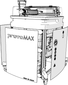
Figure 638
| 3. | Press on the center of the panel to secure it to the table frame. |
| 4. | Repeat the steps to install the remaining panels. |
Nozzle Maintenance
This section contains procedures for performing the recommended nozzle maintenance. The nozzle body lasts approximately 100 cutting hours when correctly installed, operated, and maintained. Depending on water quality, the replaceable orifice assembly last approximately 30 cutting hours, the replaceable mixing tube and nozzle filter last approximately 50 cutting hours. The life of the nozzle splash guard is dependent on the type of material being cut and the number of pierces made. See the Maintenance Schedule for the recommended frequency for this task.
Always wear safety glasses when performing maintenance on the machine.
Replace the Abrasive Tubing
The abrasive feed tube is a consumable item and wears as the abrasive flows from the garnet abrasive hopper to the nozzle body. Cracks, chips, holes, or other damage at the nozzle entrance, hopper exit, and bends along the tube can compromise the abrasive flow to the nozzle. See the Maintenance Schedule for the recommended frequency for this task.
| 1. | Open the lid and lock it in the upright position. |
Use care when opening or closing the lid to avoid injury. Never let the lid free-fall. Keep hand, fingers, or body parts away from the side of the table when closing the lid.
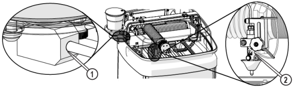
| 3. | Remove the old abrasive tube from the tube clamps [1] and the roll bar [2] and discard. |
Do not cut the abrasive feed tube. The abrasive tube is cut the length required for optimal abrasive delivery. Only use OMAX feed tube kits.
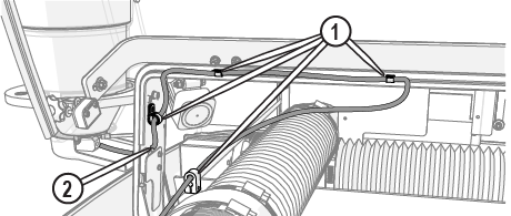
| 4. | Route the new abrasive tube from the abrasive hopper through the roll bar [2] and tube clamps [1], ensuring the abrasive tube is routed behind the cutting deck light, to the nozzle(Figure 640). |
Make sure there are no kinks in the abrasive feed tube or excessive bends along the route. Make sure there is enough slack in the abrasive tube between the connections so that the tube does not disconnect during operation.
| 5. | Insert the abrasive tube into the abrasive feed block [1] and the nozzle [2] (Figure 639). |
| 6. | Close the lid. |
| 7. | Perform a nozzle test, see Test the Nozzle. |
Rotate or Replace the Mixing Tube
Over time, the flow of high-pressure water and abrasive wears away the inside of the mixing tube. This wear results in a gradual, irregular widening of the internal diameter of the mixing tube, causing a less accurate stream of abrasive and water. A cross-section of these mixing tubes reveals the irregular wear of their internal diameter. A cross-section of these mixing tubes reveals the irregular wear of their internal diameter. Examples of normal [1], good [2], and bad [3] mixing tube wear are shown below
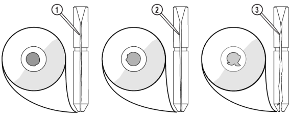
The mixing tube is very brittle and easily broken if dropped or struck hard. The key to a long mixing tube life is maintaining a healthy orifice or jewel. Damage to mixing tubes caused by misaligned jets or a damaged jewel is not apparent when looking through the bore of the mixing tube. The size of the kerf and cutting performance are the best indicators of mixing tube wear. The kerf is the width of the cut made by the abrasive waterjet. With a 0.030 in. (0.762 mm) mixing tube, it can range from 0.015 in. (0.38 mm) to 0.060 in. (1.52 mm), depending on the nozzle, the thickness of the material, and the amount of wear on the mixing tube.
A clogged mixing tube is most frequently caused by using contaminated garnet abrasive. Because the opening in the mixing tube is small, even a small particle of dirt can clog it. Other potential causes of clogging include contaminated or wet garnet abrasive. Metal chips from other shop operations and paper from the garnet abrasive bag are two common sources of contamination. To clear a clogged mixing tube, see 401434-EN Operation, ProtoMAX.
Inspect the mixing tube inlet and outlet ends to see if it needs to be replaced (Figure 641). See the Maintenance Schedule for the recommended frequency for this task.
| 1. | Open the lid and lock it in the upright position. |
Use care when opening or closing the lid to avoid injury. Never let the lid free-fall. Keep hand, fingers, or body parts away from the side of the table when closing the lid.
| 2. | Place a piece of cardboard or similar material on the cutting deck to keep the mixing tube from falling in the catcher tank. |
| 3. | Remove the nozzle splash guard [1]. |
![]()
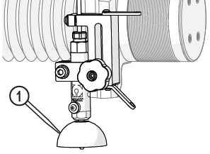
Figure 642
| 4. | Clean and inspect the splash guard for damage, replace as needed. |
| 5. | Loosen the mixing tube retainer [1] and replace or rotate the mixing tube [2] 90 degrees (one-quarter turn). |
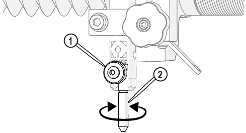
Figure 643
| 6. | Verify the mixing tube is correctly seated in the nozzle body and tighten the mixing tube retainer. |

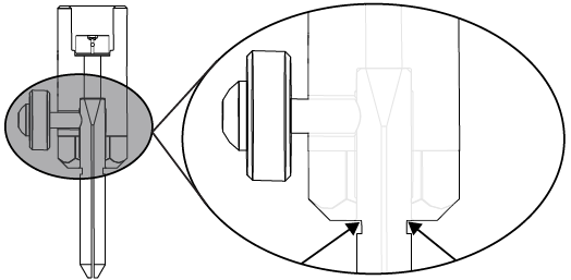
Figure 644
| 7. | Close the lid. |
| 8. | Perform a nozzle test, see Test the Nozzle. |
Clean the Orifice and Nozzle Body
The nozzle body contains a jewel that requires regular cleaning. Replace the orifice assembly if damaged. The hole in the jewel is very small, approximately 0.008 in. (0.20 mm) in diameter. Water travels through the orifice at extremely high speeds. The water, depending on the water quality, can leave mineral deposits [2] on the jewel that is difficult to see with the naked eye. Variables such as elevated water temperature and pH, plus the presence of scaling ions (calcium, magnesium, or silicone) can cause scale to build up in and around the internal diameter of the orifice. Mineral deposits, or scale, in the internal diameter of the orifice, can form a hollow cone surrounding the small hole in the center of the jewel. Eventually, this buildup results in poor jet quality and increases mixing tube wear. The jewel can also be clogged, worn, or become misaligned.
For optimal cutting, the jewel edges [1] should be clean and sharp. The center hole is completely round with no damage in the area around the hole. Mineral deposits should not be visible or clogging the hole. See the Maintenance Schedule for the recommended frequency for this task.
![]()
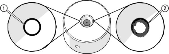
Figure 645
| 1. | Open the lid and lock it in the upright position. |
Use care when opening or closing the lid to avoid injury. Never let the lid free-fall. Keep hand, fingers, or body parts away from the side of the table when closing the lid.
| 2. | Remove the nozzle body [2] from the inlet body [1]. |

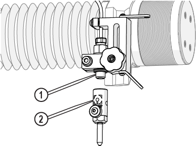
Figure 646
| 3. | Remove the orifice [1] from the nozzle body. |
![]()
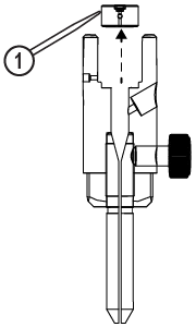
Figure 647
| 4. | Submerge the orifice and nozzle body into an ultrasonic cleaner filled with white vinegar. |
| 5. | Run the ultrasonic cleaner for 3–5 minutes or until clean. |
| 6. | Rinse the orifice and nozzle body with clean water. |
| 7. | Inspect the orifice to make sure the jewel [1] and vent hole [2] are clean and free of deposits. |
![]()
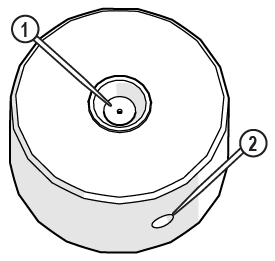
Figure 648
Do not use a brush or cotton swab or foam-tipped applicator to apply lubricants because they can leave fibers and clog the nozzle.
| 8. | Apply a light coat of Blue Goop to the second and third threads [1] of the inlet body, then spread the lubricant evenly around the inlet body threads. |
Use care when applying lubricants around high-pressure water routes. Lubricants can enter the high-pressure water system and clog the orifice.
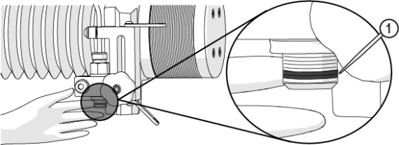
Figure 649
| 9. | Wipe the excess Blue Goop from the end of the inlet body [1]. |
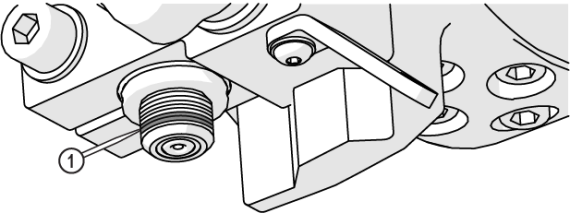
Figure 650
| 10. | Clean the nozzle and orifice assemblies. See Clean the Orifice and Nozzle Body for recommended cleaning procedures. |
| 11. | Apply a light coat of Blue Goop to the first and second nozzle body threads [1], then spread the lubricant evenly around the nozzle body threads. |
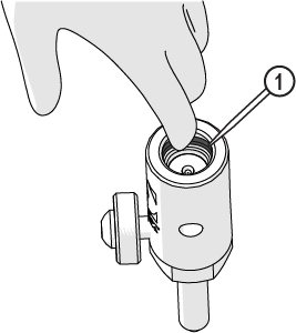
Figure 651
| 12. | Wipe the excess Blue Goop from the end of the nozzle body [1]. |
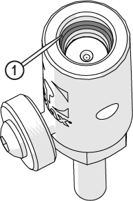
Figure 652
Always orient the orifice assembly so that the brass [1] is visible from the top of the nozzle body. Inserting the orifice assembly in nozzle body in the incorrect orientation [2] can cause damage to the orifice assembly.
![]()
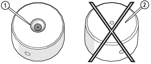
Figure 653
| 13. | Insert the orifice assembly [1] into the nozzle body and adjust the orifice to make sure it is seated correctly in the chamber bore [2]. |
![]()
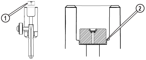
Figure 654
| 14. | Attach the nozzle [3] to the inlet body [1] and tighten. |
Ensure the garnet abrasive inlet [2] points towards the front of the table. Move the Z-axis to the back of the cutting deck (+Y direction) before tightening.

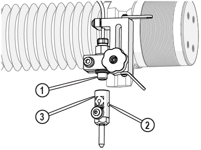
Figure 655
| 15. | Close the lid. |
| 16. | Verify the mixing tube is correctly seated into the nozzle body, and the thumbscrew is tightened. |
Figure 656
| 17. | Close the lid. |
| 18. | Reset the pump, see Reset the Pump. |
| 19. | Perform a nozzle test, see Test the Nozzle. |
Replace the Nozzle Filter
The nozzle filter removes small particles from the jet stream and is a consumable item. See the Maintenance Schedule for the recommended frequency for this task.
| 1. | Open the lid and lock it in the upright position. |
Use care when opening or closing the lid to avoid injury. Never let the lid free-fall. Keep hand, fingers, or body parts away from the side of the table when closing the lid.
| 2. | Thoroughly clean the high-pressure line and components before disassembly. |
| 3. | Place cardboard or similar material onto the cutting deck to prevent injury from sharp slats and tools/parts from dropping into the tank. |
| 4. | Remove the nozzle body [2] from the inlet body [1]. |
Figure 657
| 5. | Screw the seal removal tool into the nozzle filter. |
Do not scratch or damage the inlet body when using the seal removal tool. Doing so can cause leaking.

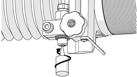
Figure 658
| 6. | Pull the seal removal tool straight down to remove the nozzle filter from the inlet body. |
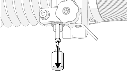
Figure 659
| 7. | Unscrew the removed nozzle filter from the removal tool and discard the old nozzle filter. |
The filter seal assembly is a consumable item and is replaceable.
| 9. | Clean and inspect the O-ring [1] for damage, replaced it as needed (Figure 660). |
| 10. | Clean both the inlet body threads [1] and the bottom surface [2]. |
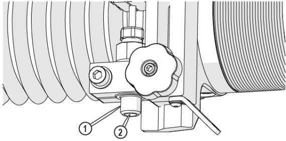
Figure 661
| 11. | Insert the nozzle filter [1] into the inlet body. |
The nozzle filter is correctly seated when tightening the nozzle body.
![]()
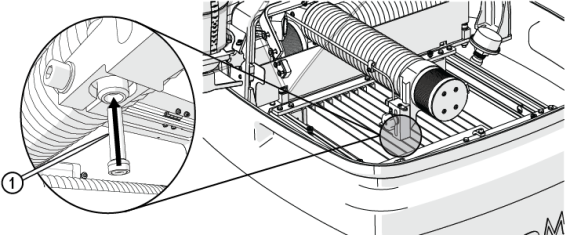
Figure 662
| 12. | Place the inlet body O-ring [1] on the inlet body. |
![]()
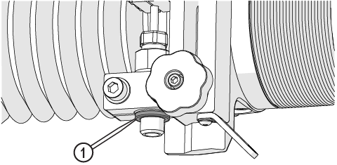
Figure 663
Do not use a brush or cotton swab or foam-tipped applicator to apply lubricants because they can leave fibers and clog the nozzle.
| 13. | Apply a light coat of Blue Goop to the second and third threads [1] of the inlet body, then spread the lubricant evenly around the inlet body threads. |
Use care when applying lubricants around high-pressure water routes. Lubricants can enter the high-pressure water system and clog the orifice.
Figure 664
| 14. | Wipe the excess Blue Goop from the end of the inlet body [1]. |
Figure 665
| 15. | Clean the nozzle and orifice assemblies. See Clean the Orifice and Nozzle Body for recommended cleaning procedures. |
| 16. | Apply a light coat of Blue Goop to the first and second nozzle body threads [1], then spread the lubricant evenly around the nozzle body threads. |
Figure 666
| 17. | Wipe the excess Blue Goop from the end of the nozzle body [1]. |
Figure 667
| 18. | Verify the orifice assembly [1] is installed in the nozzle body, adjust the orifice to make sure it is seated correctly in the chamber bore [2]. |
![]()
Figure 668
Always orient the orifice assembly so that the brass [1] is visible from the top of the nozzle body. Inserting the orifice assembly in nozzle body in the incorrect orientation [2] can cause damage to the orifice assembly.
![]()
Figure 669
| 19. | Attach the nozzle body [3] to the inlet body [1] and tighten. |
Do not overtighten the nozzle body. The ring seal and O-ring make the seal, not the torque of the body. Over tightening does not fix a leak and most likely creates additional repair issues. If there is a leak, inspect the sealing surfaces and replace the seal.
Ensure the garnet abrasive inlet [2] points towards the front of the table. Move the Z-axis to the back of the cutting deck (+Y direction) before tightening.
Figure 670
| 20. | Close the lid. |
| 21. | Perform a nozzle test, see Test the Nozzle. |
Flush the High-Pressure Plumbing
Flushing the high-pressure plumbing system makes sure there is no debris in the high-pressure plumbing that can clog the nozzle during operation.
To avoid injury or damage, make all water and high-pressure connections before continuing. Contact OMAX Technical Support if needed
| 1. | Remove the nozzle body [2] and the nozzle filter [1] from the inlet body. Discard the nozzle filter. |
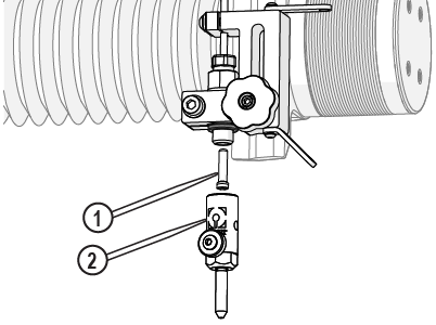
Figure 671
Hold the inlet body when loosening the hand knob. Do not let the inlet body fall and strike the cutting deck slats. Damage to the inlet body can occur, which can cause leaks.
| 2. | Loosen the Z-axis [1] and lower it to the lowest position. |
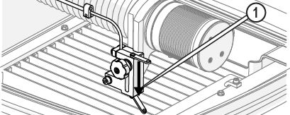
| 3. | Close the lid. |
Use care when opening or closing the lid to avoid injury. Never let the lid free-fall. Keep hand, fingers, or body parts away from the side of the table when closing the lid.
| 4. | Open the main water source, if needed. |
| 5. | Push the button [1] on the water filter to release the air. |
Place a rag over the top of the water filter to prevent water from spraying.
Figure 673
| 6. | In MAKE, use the X, Y Jog buttons [1], or the keyboard arrow keys to position the nozzle between two slats in the center of the cutting deck. |
![]()
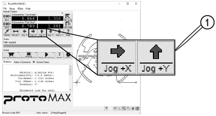
Figure 674
| 7. | Click Test [1]. |
![]()
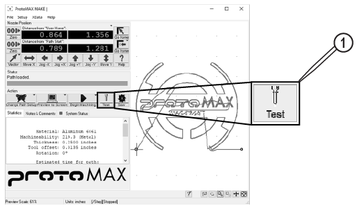
Figure 675
| 8. | In the Test Operations dialog box, select Flush plumbing, click Next. |
![]()
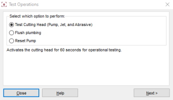
Figure 676
Keep a minimum of 16 in. (40 cm) away from pressurized equipment during operation. Do not try to tighten ultra-high-pressure (UHP) fittings while the system is under pressure. Do not touch or rub suspected high-pressure plumbing leaks. Rubbing or touching suspected high-pressure leaks can result in injury. If a leak is found, shut down the machine, then fix the leak before continuing. Never attempt to fix a leak while the ProtoMAX is running.
| 9. | Click Start Flush. |
The flush test runs for 30 minutes. The pump cycles on and off during the test operation, but water still flows. The test automatically stops after 30 minutes.
| 10. | Check the high-pressure plumbing for leaks at the nozzle [1], high-pressure fittings [2], and pump connection [3] during the test operation. |
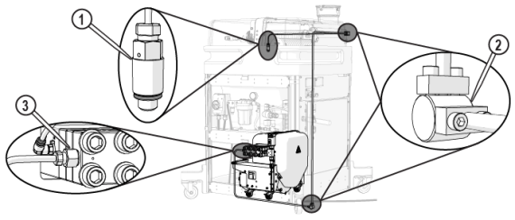
| 11. | Click Close when the flush is complete. |
| 12. | Wipe off the inlet body threads and the bottom surface of the inlet body before installing the filter and nozzle assembly. |
Install the Nozzle
| 1. | Open the lid and lock it in the upright position. |
Use care when opening or closing the lid to avoid injury. Never let the lid free-fall. Keep hand, fingers, or body parts away from the side of the table when closing the lid.
![]()
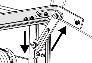
Figure 678
| 2. | Place a piece of cardboard or other material on top of the slats to keep small parts from falling into the tank. |
Hold the inlet body when loosening the hand knob. Do not let the inlet body fall and strike the cutting deck slats. Damage to the inlet body can occur, which can cause leaks.
| 3. | Raise the Z-axis. |
| 4. | Install the nozzle filter [1] into the inlet body. |
![]()
Figure 679
Do not use a brush or cotton swab or foam-tipped applicator to apply lubricants because they can leave fibers and clog the nozzle.
| 5. | Apply a light coat of Blue Goop to the second and third threads [1] of the inlet body, then spread the lubricant evenly around the inlet body threads. |
Use care when applying lubricants around high-pressure water routes. Lubricants can enter the high-pressure water system and clog the orifice.
Figure 680
| 6. | Wipe the excess Blue Goop from the end of the inlet body [1]. |
Figure 681
| 7. | Clean the nozzle and orifice assemblies. See Clean the Orifice and Nozzle Body for recommended cleaning procedures. |
| 8. | Apply a light coat of Blue Goop to the first and second nozzle body threads [1], then spread the lubricant evenly around the nozzle body threads. |
Figure 682
| 9. | Wipe the excess Blue Goop from the end of the nozzle body [1]. |
Figure 683
Always orient the orifice assembly so that the brass [1] is visible from the top of the nozzle body. Inserting the orifice assembly in nozzle body in the incorrect orientation [2] can cause damage to the orifice assembly.
![]()
Figure 684
| 10. | Make sure the orifice assembly [1] is seated correctly in the nozzle body chamber bore [2]. |
![]()
Figure 685
| 11. | Attach the nozzle [3] to the inlet body [1] and tighten. |
Ensure the garnet abrasive inlet [2] points towards the front of the table. Move the Z-axis to the back of the cutting deck (+Y direction) before tightening.
Figure 686
| 12. | Make sure the mixing tube is correctly seated in the nozzle body and the thumbscrew is tightened. |
Figure 687
| 13. | Place the nozzle splash guard onto the mixing tube, then fold the splash guard cup. |
![]()
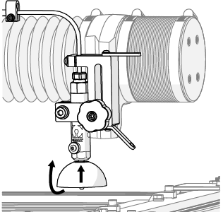
Figure 688
| a. | Open the lid and lock it in the upright position. |
Use care when opening or closing the lid to avoid injury. Never let the lid free-fall. Keep hand, fingers, or body parts away from the side of the table when closing the lid.

Figure 689
Make sure the abrasive feed tube is not connected to the nozzle.
![]()
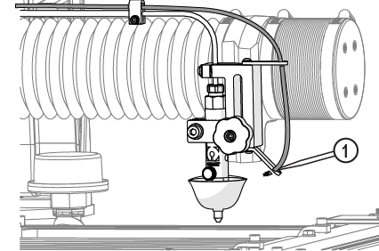
Figure 690
| b. | Position the nozzle in the center of the tank, between two slats. |

Figure 691
| c. | Close the lid. |
Use care when opening or closing the lid to avoid injury. Never let the lid free-fall. Keep hand, fingers, or body parts away from the side of the table when closing the lid.
| d. | Click Test [1]. |

Figure 692
| e. | In Test Operations, select Test Cutting Head (Pump, Jet, and Abrasive), and click Next. |

Figure 693
| f. | Click Start Test. |

Figure 694
| g. | Click Close when the test is complete. |
| 2. | Conduct a nozzle test with abrasive. |
| a. | Insert the abrasive feed tube into the garnet abrasive inlet [1]. |
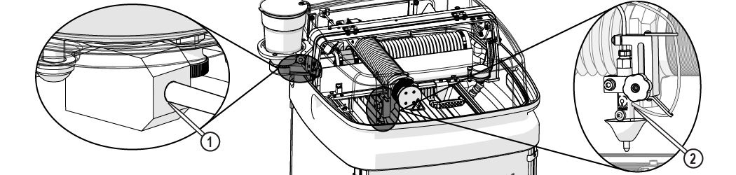
Figure 695
| b. | Click Test [1]. |
Figure 696
| c. | In Test Operations, select Test Cutting Head (Pump, Jet, and Abrasive), and click Next. |
Figure 697
| d. | Click Start Test. |
Figure 698
| e. | Observe the garnet abrasive tube [1] to make sure that the abrasive is flowing. |

Figure 699
| f. | Click Close when the test is complete. |
The nozzle test automatically stops and closes the Test in progress window after 60 seconds.
Technical Support
Refer to the ProtoMAX website for technical support contact information.
Warranty
Contact Customer Support or go to the ProtoMAX website.