Clean the Orifice and Nozzle Body
The nozzle body contains a jewel that requires regular cleaning. Replace the orifice assembly if damaged. The hole in the jewel is very small, approximately 0.008 in. (0.20 mm) in diameter. Water travels through the orifice at extremely high speeds. The water, depending on the water quality, can leave mineral deposits [2] on the jewel that is difficult to see with the naked eye. Variables such as elevated water temperature and pH, plus the presence of scaling ions (calcium, magnesium, or silicone) can cause scale to build up in and around the internal diameter of the orifice. Mineral deposits, or scale, in the internal diameter of the orifice, can form a hollow cone surrounding the small hole in the center of the jewel. Eventually, this buildup results in poor jet quality and increases mixing tube wear. The jewel can also be clogged, worn, or become misaligned.
For optimal cutting, the jewel edges [1] should be clean and sharp. The center hole is completely round with no damage in the area around the hole. Mineral deposits should not be visible or clogging the hole. See the Maintenance Schedule for the recommended frequency for this task.
![]()
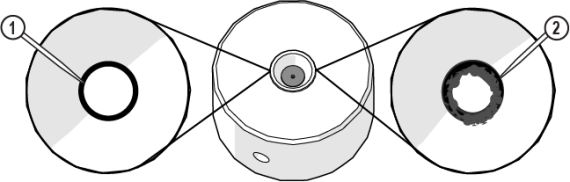
Figure 894
| 1. | Open the lid and lock it in the upright position. |
Use care when opening or closing the lid to avoid injury. Never let the lid free-fall. Keep hand, fingers, or body parts away from the side of the table when closing the lid.
| 2. | Remove the nozzle body [2] from the inlet body [1]. |

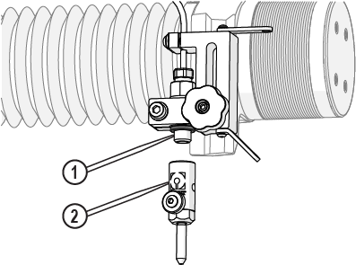
Figure 895
| 3. | Remove the orifice [1] from the nozzle body. |
![]()
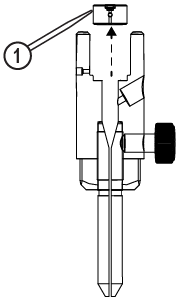
Figure 896
| 4. | Submerge the orifice and nozzle body into an ultrasonic cleaner filled with white vinegar. |
| 5. | Run the ultrasonic cleaner for 3–5 minutes or until clean. |
| 6. | Rinse the orifice and nozzle body with clean water. |
| 7. | Inspect the orifice to make sure the jewel [1] and vent hole [2] are clean and free of deposits. |
![]()
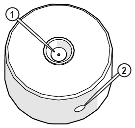
Figure 897
Do not use a brush or cotton swab or foam-tipped applicator to apply lubricants because they can leave fibers and clog the nozzle.
| 8. | Apply a light coat of Blue Goop to the second and third threads [1] of the inlet body, then spread the lubricant evenly around the inlet body threads. |
Use care when applying lubricants around high-pressure water routes. Lubricants can enter the high-pressure water system and clog the orifice.


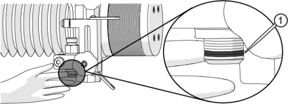
Figure 898
| 9. | Wipe the excess Blue Goop from the end of the inlet body [1]. |

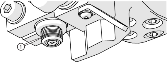
Figure 899
| 10. | Clean the nozzle and orifice assemblies. See Clean the Orifice and Nozzle Body for recommended cleaning procedures. |
| 11. | Apply a light coat of Blue Goop to the first and second nozzle body threads [1], then spread the lubricant evenly around the nozzle body threads. |
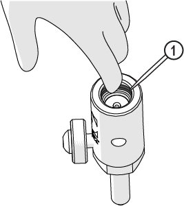
Figure 900
| 12. | Wipe the excess Blue Goop from the end of the nozzle body [1]. |
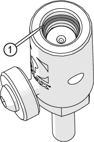
Figure 901
Always orient the orifice assembly so that the brass [1] is visible from the top of the nozzle body. Inserting the orifice assembly in nozzle body in the incorrect orientation [2] can cause damage to the orifice assembly.
![]()
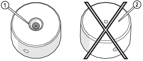
Figure 902
| 13. | Insert the orifice assembly [1] into the nozzle body and adjust the orifice to make sure it is seated correctly in the chamber bore [2]. |
![]()
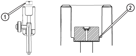
Figure 903
| 14. | Attach the nozzle [3] to the inlet body [1] and tighten. |
Ensure the garnet abrasive inlet [2] points towards the front of the table. Move the Z-axis to the back of the cutting deck (+Y direction) before tightening.


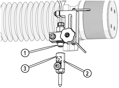
Figure 904
| 15. | Close the lid. |
| 16. | Verify the mixing tube is correctly seated into the nozzle body, and the thumbscrew is tightened. |


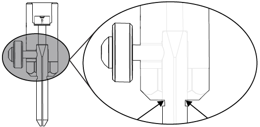
Figure 905
| 17. | Close the lid. |
| 18. | Reset the pump, see Reset the Pump. |
| 19. | Perform a nozzle test, see Test the Nozzle. |