Lubricate the Y-Axis Lead Screw and Linear Rail Bearing Carriage
| 1. | Open the lid and lock it in the upright position. |
Use care when opening or closing the lid to avoid injury. Never let the lid free-fall. Keep hand, fingers, or body parts away from the side of the table when closing the lid.
| 2. | Move the Z-axis to the middle of the cutting deck. |
| 3. | Turn OFF the machine and close MAKE. |
To avoid damage, do not use flammable liquids or other chemicals to clean the equipment.
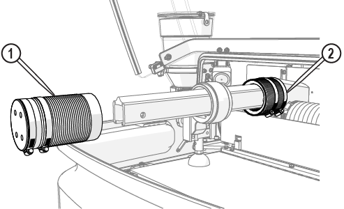
| 4. | Rinse and wipe away all debris from the bellows [1]. |


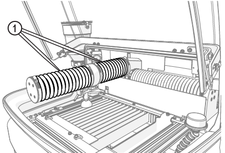
Figure 814
| 5. | Place a piece of cardboard on the cutting deck to keep components or tools from falling in the catcher tank. |
| 6. | Loosen the center clamps [1]. |
Do not move the bellows away from the Y-axis carriage. The area around the Y-carriage must be clean of debris to prevent erosion damage to the internal components.

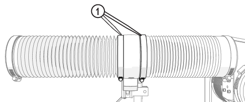
Figure 815
| 7. | Push up on the bottom of the clamps [1] to loosen, then slide the clamps toward the ends. |
Clamps can stick to the bellows. To prevent damage to the bellows, use care when removing the clamps.

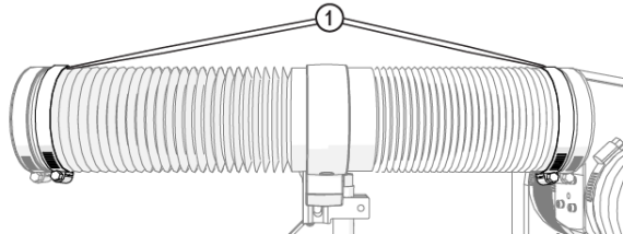
Figure 816
| 8. | Wipe the bellows ends [1] and Y-axis carriage with a clean rag; remove all debris. |

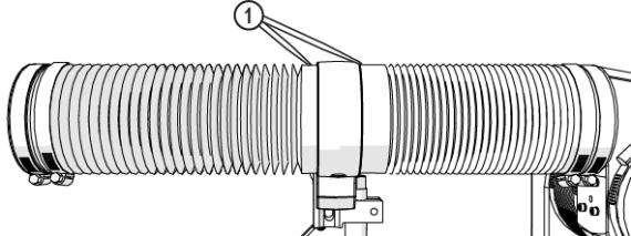
Figure 817
| 9. | Remove the end cap screws [1] and set aside. |

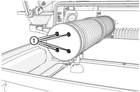
Figure 818
Use care when removing the bellows from the Y-axis carriage. Ripping or tearing of the bellows ends can allow debris in the Y-axis and can cause damage to the internal components.
| 11. | Slide the rear bellows [2] from the Y-axis carriage (Figure 819). |
| 12. | Clean all debris from around the lead screw nut [1] with a dry, soft cloth. |

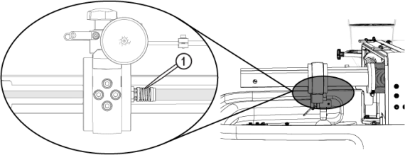
Figure 820
| 13. | Apply a light coat of lubricant, approximately a 1/8 in. bead, along the length of the lead screw [1]. |


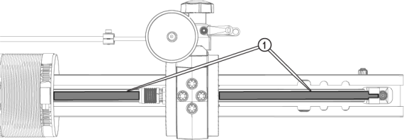
Figure 821
| 14. | Turn ON the machine and open MAKE. |
| 15. | Using MAKE, move the Y-axis the full length of travel three times. |

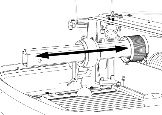
Figure 822
| 16. | Wipe off any excess lubricant. |

| 17. | Close MAKE and turn OFF the machine. |
Rotating the bellows helps to eliminate rub marks or holes on the interior of the bellows, prolongs the bellows life. If needed, loosen the clamp at both ends of the bellows, rotate the bellows approximately 90 degrees then secure with the clamps.
| 18. | Reattach the rear bellows to the Y-axis carriage, pulling the bellows lip over the Y-axis carriage edge. |
Ensure there is an even gap [1] between the Y-axis carriage housing and the bellows lip to keep debris from entering into the bellows and causing damage to the interior components.

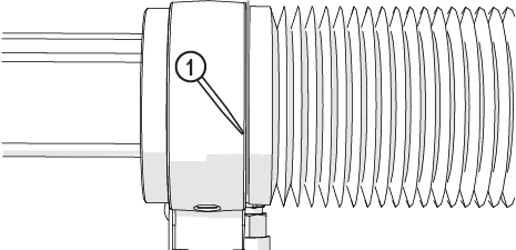
Figure 823
| 19. | Secure the bellows with the clamp [1]. |
Make sure the bellows cuff does not move away or come off while tightening the clamp.

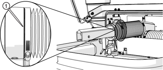
Figure 824
| 20. | Turn ON the machine, move the Z-axis forward until it reaches the hard stop. |
| 21. | Turn OFF the machine. |

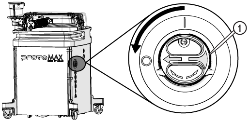
Figure 825
| 22. | Identify if the lead screw support bracket configuration, then complete the applicable procedure. |
| • | If there is access [1] to the grease port, go to Lubricate the Y-Axis Linear Rail Bearing Carriage with Grease Port Access. |

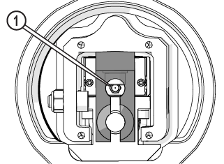
Figure 826
| • | If there is no access [1] to the grease port, go to Lubricate the Y-Axis Linear Rail Bearing Carriage without Grease Port Access. |

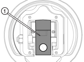
Figure 827
