Replace the Safety Valve
Never attempt to adjust the safety valve; doing so creates a safety hazard and voids the warranty!
The safety valve functions to prevent excessive build-up of water pressure in the high-pressure plumbing system. During normal operation, the pump can reach extremely high pressures. When excessive-high pressures are detected, the variable frequency drive (VFD) slowly lowers the motor’s revolutions per minute (RPM) to prevent over-pressuring the system. If lowering the RPM does not prevent an overpressure condition, the safety valve activates when the factory preset pressure is reached (approximately 38 ksi), releasing the excess pressure.
Replacing the safety valve is required when leaking occurs during normal cutting operations.
If leaking continues to occur or if the calibration seal [1] has been broken, tampered with, or damaged, replacement of the safety valve assembly is required.
![]()
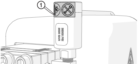
Figure 722
| 1. | Turn OFF the machine. |
![]()
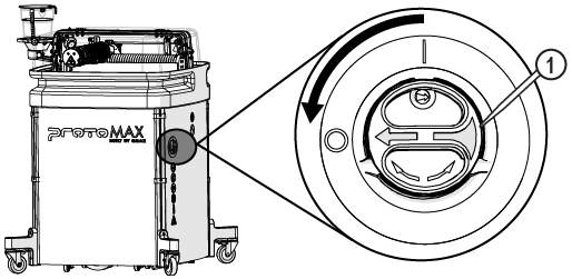
Figure 723
| 2. | Remove the front and right side panels. |
| 3. | Disconnect the pump power cable. |
![]()
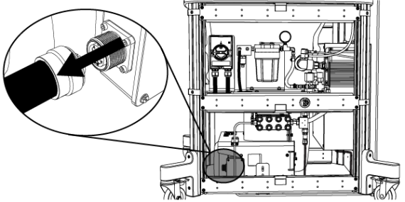
Figure 724
| 4. | Ensure there is no pressurized water in the high-pressure lines. |
| a. | Open the lid and lock it in the upright position. |
Use care when opening or closing the lid to avoid injury. Never let the lid free-fall. Keep hand, fingers, or body parts away from the side of the table when closing the lid.
| b. | Loosen the gland nut [1] to release the pressure; water can leak from the inlet body weep hole. |


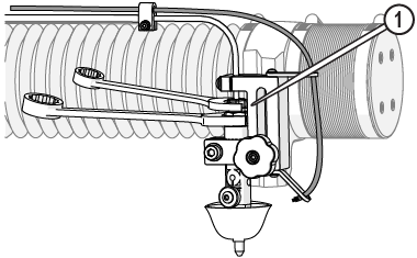
Figure 725
| c. | Tighten the gland nut [1]. |


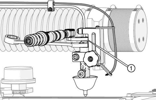
Figure 726
| 5. | Disconnect the transducer cable [1]. |
Protect the connecting ends from external contamination or debris. Debris can enter into the high-pressure plumbing system and damage the pump or nozzle.
![]()
![]()
Figure 727
| 6. | Loosen the T-fitting gland nut. |


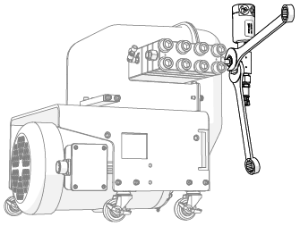
Figure 728
| 7. | Rotate the safety valve assembly counterclockwise until it contacts the water hose and can rotate no more. |
Safety valve internal components are loose and can fall out if the safety valve is removed while positioned vertically. Rotating the safety valve assembly to a more horizontal position before removal makes it more difficult for internal components to fall out on their own.
| 8. | Remove the safety valve [1]. |
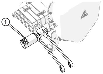
Figure 729
| 9. | Carefully remove the protective cap from the new safety valve. |
The protective cap keeps debris from contaminating the safety valve interior and keeps the internal components [1] from falling out. Always hold the safety valve with the stem up when removing the protective cap to keep the internal components from falling out and becoming contaminated with debris.
![]()
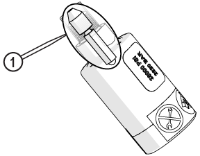
Figure 730
Avoid areas where Blue Goop can enter into the high-pressure water system (the tip of the safety valve body and the tip of the seat). Do not apply excessive amounts of Blue Goop onto the threads or seat of the safety valve. Excess Blue Goop can enter into the high-pressure water system and cause damage.
| 10. | Apply a very light coat of Blue Goop onto the coned end of the seat [1] and the threads [2] of the safety valve, if not already applied. |


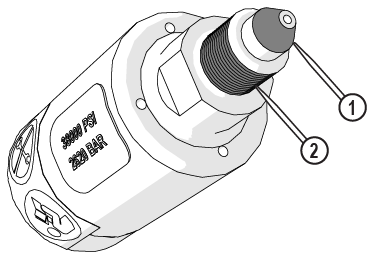
Figure 731
| 11. | Install the safety valve [1] onto the T-fitting [2] then hand-tighten. |
![]()
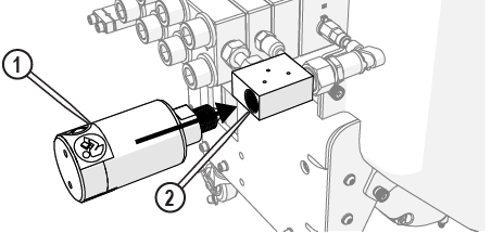
Figure 732
The jaws of the crowfoot must maintain a 90-degree angle to the horizontal axis of the torque-wrench handle throughout the torquing rotation. Other angles of orientation can alter the set torque.
![]()
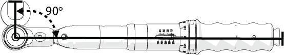
Figure 733
| 12. | Torque the safety valve [1]. |


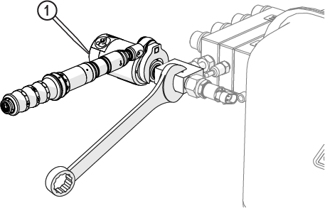
Figure 734
| 13. | Rotate the safety valve so that it is perpendicular to the floor. |
| 14. | Torque the T-fitting gland nut. |

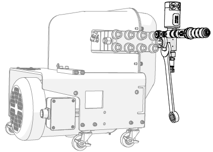
Figure 735
| 15. | Apply a heavy coat of dielectric compound to the transducer cable [2], then connect the transducer cable to the transducer [1]. |

![]()
Figure 736
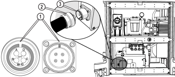
| 16. | Apply a heavy coat of dielectric compound to the power cord plug [2] (Figure 737). |
| 17. | Aline the notches [1] on the power cord plug and power connector [3], then push until the power cord plug seats in the power connector(Figure 737). |
| 18. | Rotate the shell counterclockwise until the threads engage, then turn the shell clockwise to tighten. |
| 19. | Flush the high-pressure plumbing, see Flush the High-Pressure Plumbing. |
| 20. | Reset the pump, see Reset the Pump. |
| 21. | Install the nozzle, if removed, see Install the Nozzle, perform a nozzle test, and see Test the Nozzle. |
| 22. | With the pump running at high pressure, carefully inspect the safety valve for signs of water leakage. Correct all leakage problems before continuing. |
| 23. | Replace the side panels, see Install the Side Panels. |