Install the Nozzle
| 1. | Open the lid and lock it in the upright position. |
Use care when opening or closing the lid to avoid injury. Never let the lid free-fall. Keep hand, fingers, or body parts away from the side of the table when closing the lid.
![]()
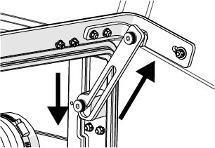
Figure 927
| 2. | Place a piece of cardboard or other material on top of the slats to keep small parts from falling into the tank. |
Hold the inlet body when loosening the hand knob. Do not let the inlet body fall and strike the cutting deck slats. Damage to the inlet body can occur, which can cause leaks.
| 3. | Raise the Z-axis. |
| 4. | Install the nozzle filter [1] into the inlet body. |
![]()
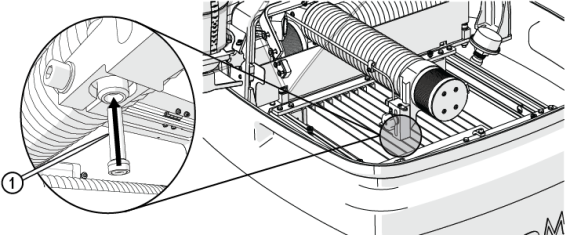
Figure 928
Do not use a brush or cotton swab or foam-tipped applicator to apply lubricants because they can leave fibers and clog the nozzle.
| 5. | Apply a light coat of Blue Goop to the second and third threads [1] of the inlet body, then spread the lubricant evenly around the inlet body threads. |
Use care when applying lubricants around high-pressure water routes. Lubricants can enter the high-pressure water system and clog the orifice.


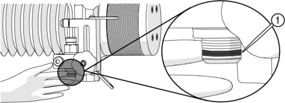
Figure 929
| 6. | Wipe the excess Blue Goop from the end of the inlet body [1]. |

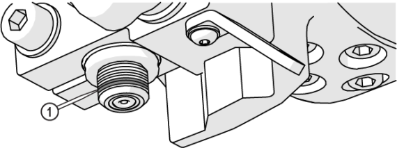
Figure 930
| 7. | Clean the nozzle and orifice assemblies. See Clean the Orifice and Nozzle Body for recommended cleaning procedures. |
| 8. | Apply a light coat of Blue Goop to the first and second nozzle body threads [1], then spread the lubricant evenly around the nozzle body threads. |
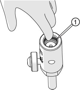
Figure 931
| 9. | Wipe the excess Blue Goop from the end of the nozzle body [1]. |
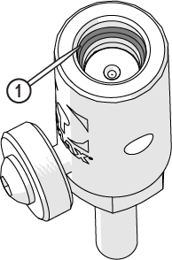
Figure 932
Always orient the orifice assembly so that the brass [1] is visible from the top of the nozzle body. Inserting the orifice assembly in nozzle body in the incorrect orientation [2] can cause damage to the orifice assembly.
![]()
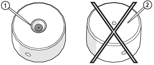
Figure 933
| 10. | Make sure the orifice assembly [1] is seated correctly in the nozzle body chamber bore [2]. |
![]()
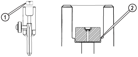
Figure 934
| 11. | Attach the nozzle [3] to the inlet body [1] and tighten. |
Ensure the garnet abrasive inlet [2] points towards the front of the table. Move the Z-axis to the back of the cutting deck (+Y direction) before tightening.


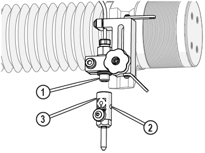
Figure 935
| 12. | Make sure the mixing tube is correctly seated in the nozzle body and the thumbscrew is tightened. |


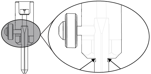
Figure 936
| 13. | Place the nozzle splash guard onto the mixing tube, then fold the splash guard cup. |
![]()
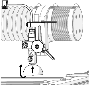
Figure 937