Connect the High-Pressure Plumbing
When preparing the ProtoMAX high-pressure tubing, it is critical to follow instructions. Some high-pressure tubing and fittings are pre-assembled. Fittings may need readjustment during installation to make sure proper seals and eliminate potential leaks. Use the provided Stand-off tool to make sure the fittings are correctly seated and sealed.
| 1. | Verify the u-shape high-pressure nipple, gland nut, slotted collet, and collar are assembled and aligned. See High-Pressure Gland Nut Assembly. |
High-pressure nipples have left-hand threads, therefore when connecting components, turn clockwise to loosen and counterclockwise tighten. Cross threading high-pressure connections can cause leaks or water damage from the leak(s).
| 2. | Verify the collar [1] is installed in the correct position using the stand-off tool [2], then adjust the collar to the correct depth if needed. |

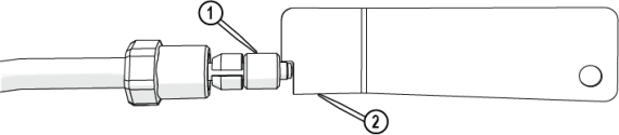
Figure 744
| 3. | Position the pump so that the high-pressure plumbing is aligned vertically and horizontally, and the rear of the pump is 1–2 in. from the control cabinet. |
![]()
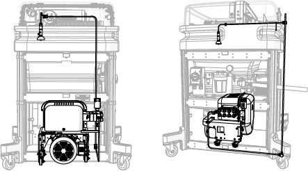
Figure 745
| 4. | Attach the assembled u-shape nipple [1] to the pump high-pressure outlet OUT connection [2] and hand-tighten. |
![]()

Figure 746
| 5. | Verify the gland nut [2] is set approximately to the depth of the nozzle stand-off tool [1]. |
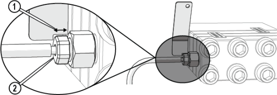
Figure 747
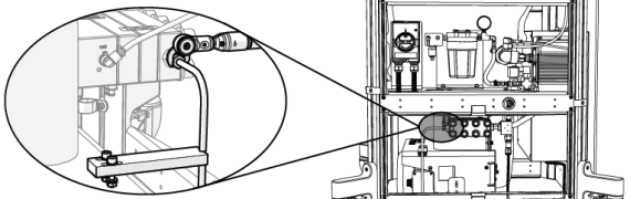
| 6. | Adjust the position of the bracket [1], then tighten the bracket. |


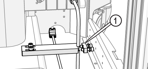
Figure 748
| 7. | Lock the pump wheels [1]. |
![]()
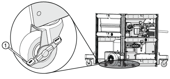
Figure 749
| 8. | Torque the pump connection (Figure 751). |
The jaws of the crowfoot must maintain a 90-degree angle to the horizontal axis of the torque-wrench handle throughout the torquing rotation. Other angles of orientation can alter the set torque.
![]()
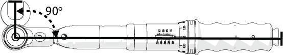
Figure 750


| 9. | Attach the bracket cap [1] and tighten. |
Move the conduit out of the way so that it is not trapped under the bracket.

Figure 752
| 10. | Reinstall the front support bracket [1] with the provided hardware. |

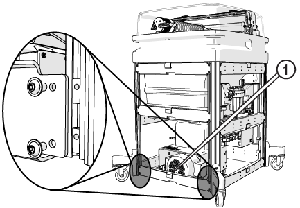
Figure 753