Maintain the Nozzle High-Pressure Gland Nut
When preparing the ProtoMAX high-pressure tubing, it is important to follow instructions. Some high-pressure tubing and fittings are pre-assembled. Fittings may need readjustment during installation to make proper seals and eliminate potential leaks. Use the provided stand-off tool to make sure the fittings are correctly seated and sealed.
Nipples contain small caps to protect the threading and keep debris from entering the high-pressure plumbing during shipment. Remove the caps before assembling the high-pressure plumbing fittings. Do not use pliers to remove the black caps or cut the black caps from the nipple. Pliers and knives damage the nipple threads causing leaks in the high-pressure lines and water damage.
| 1. | Release any pressurized water from the high-pressure lines, see Prepare the High-Pressure Lines for Repair. |
| 2. | Raise the Z-axis approximately 1 in. (3 cm). |
| 3. | Completely loosen the gland nut [1] from the inlet body. |


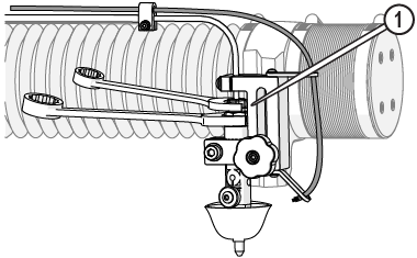
Figure 785
| 4. | If replacing the high-pressure line, loosen and remove the high-pressure fitting that is on the end of the high-pressure line that extends out from the back of the machine. See Maintain the High-pressure Fittings for removal instructions. |
| 5. | Loosen or remove the Z-axis tubing clamp [1]. |

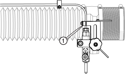
Figure 786
| 6. | Replace the damaged component. |
If replacing the high-pressure nipple, remove the tubing clamp [1] and disassemble the fitting at the rear of the cutting deck, see Maintain the High-Pressure Fittings, remove the old nipple from the conduit, then insert the new nipple in the conduit and reattach the tubing clamp.


Figure 787
| 7. | Rotate the nipple cap clockwise to remove it and make sure that there is no debris in the high-pressure tube, if needed. |
![]()
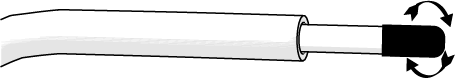
Figure 788
| 9. | Place the slotted collet [2] on the nipple with the tapered end facing the gland nut [1] (Figure 789). |
| 10. | Thread the collar [3] on to the nipple(Figure 789). |
| 11. | Use the stand-off tool [1] to set the collar depth. |
High-pressure nipples have left-hand threads, therefore when connecting components, turn clockwise to loosen and counterclockwise tighten. Cross threading high-pressure connections can cause leaks and water damage from the leak(s).
| 12. | Support the high-pressure tube [1], so the nipple is perpendicular [2] to the inlet body [3], then attach the gland nut to the inlet body and hand-tighten (Figure 789) |
![]()
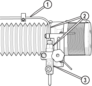
Figure 791
| 13. | Torque the gland nut [1]. |


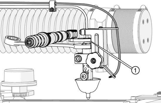
Figure 792
| 14. | Attach the z-axis tubing clamp [1]. |
Figure 793
| 15. | Install and tighten the nipple tubing clamp [1]. |
Figure 794
| 16. | Flush the high-pressure plumbing, see Flush the High-Pressure Plumbing. |
| 17. | Reset the pump, see Reset the Pump. |
| 18. | Install the nozzle, if removed, see Install the Nozzle, perform a nozzle test, and see Test the Nozzle. |
Maintain the Pump High-Pressure Gland Nut
When preparing the ProtoMAX high-pressure tubing, it is important to follow instructions. Some high-pressure tubing and fittings are pre-assembled. Fittings may need readjustment during installation to make proper seals and eliminate potential leaks. Use the provided stand-off tool to make sure the fittings are correctly seated and sealed.
Nipples contain small caps to protect the threading and keep debris from entering the high-pressure plumbing during shipment. Remove the caps before assembling the high-pressure plumbing fittings. Do not use pliers to remove the black caps or cut the black caps from the nipple. Pliers and knives damage the nipple threads causing leaks in the high-pressure lines and water damage.
| 1. | Thoroughly clean all high-pressure components before disassembly. |
| 2. | Release any pressurized water from the high-pressure lines, see Prepare High-Pressure Lines for Repair. |
| 3. | Loosen the gland nut. |

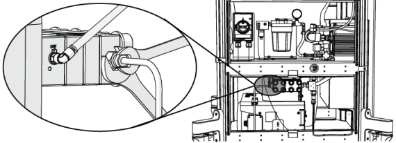
Figure 795
| 4. | Remove the bracket cap [1]. |


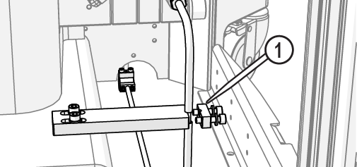
Figure 796
| 5. | Replace the damaged component. |
If replacing the high-pressure nipple, disassemble the fitting at the rear of the machine, see Maintain the High-Pressure Fittings, then remove the old nipple from the conduit, then insert the new nipple in the conduit.
| 6. | Rotate the nipple cap clockwise to remove it and verify there is no debris in the high-pressure tube. |
![]()
Figure 797
| 7. | Place the gland nut [1] on the nipple. |
![]()
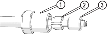
Figure 798
| 8. | Place the slotted collet [2] on the nipple with the tapered end facing the gland nut [1] and thread the collar [3] on the nipple (Figure 95). |
| 9. | Use the stand-off tool [1] to verify the collar depth. |
High-pressure nipples have left-hand threads, therefore when connecting components, turn clockwise to loosen and counterclockwise to tighten. Cross threading high-pressure connections cause leaks and water damage from the leak(s).
![]()
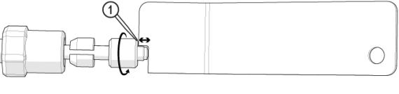
Figure 799
| 10. | Position the pump so that the high-pressure plumbing is aligned vertically and horizontally, and the rear of the pump is 1–2 in. (3–5 cm) from the control cabinet. |
![]()
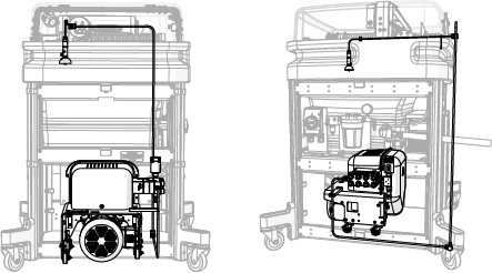
Figure 800
| 11. | Attach the assembled u-shape nipple [1] to the pump high-pressure outlet OUT connection [2] and hand-tighten. |
![]()

Figure 801
| 12. | Verify the gland nut [2] is set approximately to the depth of the nozzle stand-off tool [1]. |

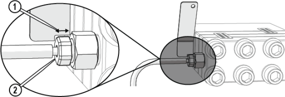
Figure 802
| 13. | Adjust the position of the bracket [1], then tighten the bracket. |
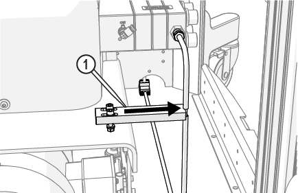
Figure 803
| 14. | Lock the pump wheels [1]. |
![]()
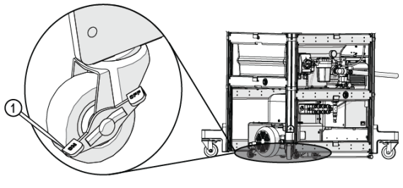
Figure 804
The jaws of the crowfoot must maintain a 90-degree angle to the horizontal axis of the torque-wrench handle throughout the torquing rotation. Other angles of orientation can alter the set torque.
![]()
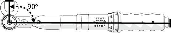
Figure 805
| 15. | Torque the pump connection. |
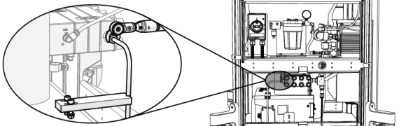
Figure 806
| 16. | Attach the bracket cap [1] and tighten. |
Move the conduit out of the way so that it is not trapped under the bracket.
Figure 807
| 17. | Flush the high-pressure plumbing, see Flush the High-Pressure Plumbing. |
| 18. | Reset the pump, see Reset the Pump. |
| 19. | Install the nozzle, if removed, see Install the Nozzle, perform a nozzle test, and see Test the Nozzle. |