Replace the Nozzle Filter
The nozzle filter removes small particles from the jet stream and is a consumable item. See the Maintenance Schedule for the recommended frequency for this task.
| 1. | Open the lid and lock it in the upright position. |
Use care when opening or closing the lid to avoid injury. Never let the lid free-fall. Keep hand, fingers, or body parts away from the side of the table when closing the lid.
| 2. | Thoroughly clean the high-pressure line and components before disassembly. |
| 3. | Place cardboard or similar material onto the cutting deck to prevent injury from sharp slats and tools/parts from dropping into the tank. |
| 4. | Remove the nozzle body [2] from the inlet body [1]. |

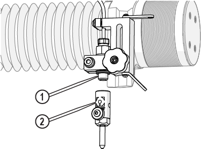
Figure 906
| 5. | Screw the seal removal tool into the nozzle filter. |
Do not scratch or damage the inlet body when using the seal removal tool. Doing so can cause leaking.

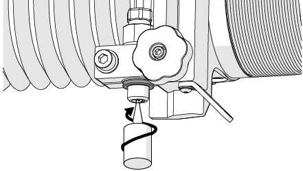
Figure 907
| 6. | Pull the seal removal tool straight down to remove the nozzle filter from the inlet body. |
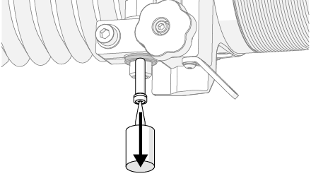
Figure 908
| 7. | Unscrew the removed nozzle filter from the removal tool and discard the old nozzle filter. |
The filter seal assembly is a consumable item and is replaceable.
| 9. | Clean and inspect the O-ring [1] for damage, replaced it as needed (Figure 909). |
| 10. | Clean both the inlet body threads [1] and the bottom surface [2]. |

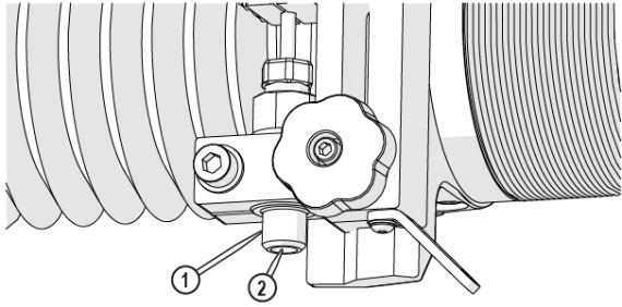
Figure 910
| 11. | Insert the nozzle filter [1] into the inlet body. |
The nozzle filter is correctly seated when tightening the nozzle body.
![]()
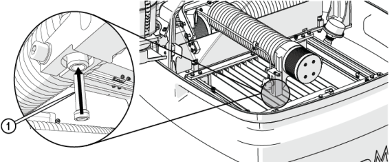
Figure 911
| 12. | Place the inlet body O-ring [1] on the inlet body. |
![]()
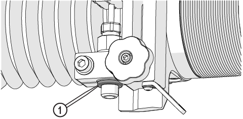
Figure 912
Do not use a brush or cotton swab or foam-tipped applicator to apply lubricants because they can leave fibers and clog the nozzle.
| 13. | Apply a light coat of Blue Goop to the second and third threads [1] of the inlet body, then spread the lubricant evenly around the inlet body threads. |
Use care when applying lubricants around high-pressure water routes. Lubricants can enter the high-pressure water system and clog the orifice.


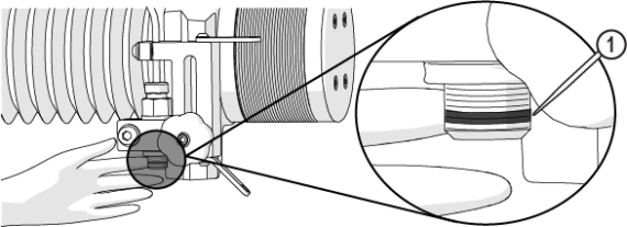
Figure 913
| 14. | Wipe the excess Blue Goop from the end of the inlet body [1]. |
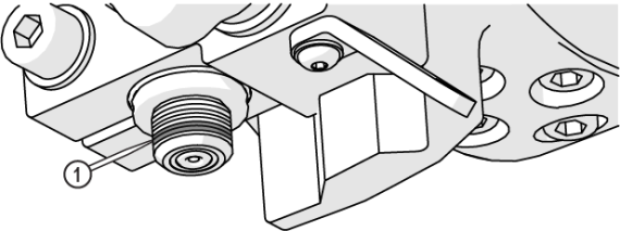
Figure 914
| 15. | Clean the nozzle and orifice assemblies. See Clean the Orifice and Nozzle Body for recommended cleaning procedures. |
| 16. | Apply a light coat of Blue Goop to the first and second nozzle body threads [1], then spread the lubricant evenly around the nozzle body threads. |
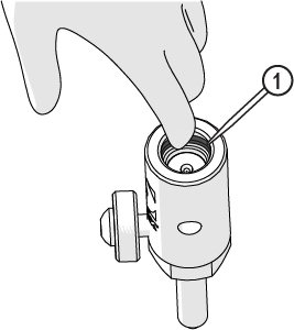
Figure 915
| 17. | Wipe the excess Blue Goop from the end of the nozzle body [1]. |
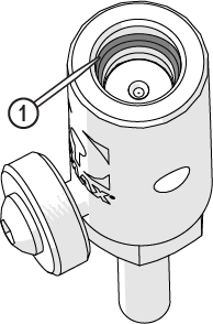
Figure 916
| 18. | Verify the orifice assembly [1] is installed in the nozzle body, adjust the orifice to make sure it is seated correctly in the chamber bore [2]. |
![]()
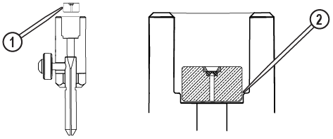
Figure 917
Always orient the orifice assembly so that the brass [1] is visible from the top of the nozzle body. Inserting the orifice assembly in nozzle body in the incorrect orientation [2] can cause damage to the orifice assembly.
![]()
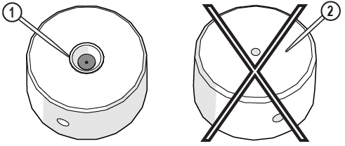
Figure 918
| 19. | Attach the nozzle body [3] to the inlet body [1] and tighten. |
Do not overtighten the nozzle body. The ring seal and O-ring make the seal, not the torque of the body. Over tightening does not fix a leak and most likely creates additional repair issues. If there is a leak, inspect the sealing surfaces and replace the seal.
Ensure the garnet abrasive inlet [2] points towards the front of the table. Move the Z-axis to the back of the cutting deck (+Y direction) before tightening.


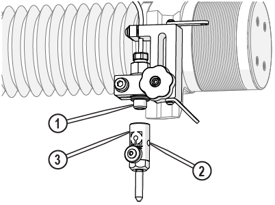
Figure 919
| 20. | Close the lid. |
| 21. | Perform a nozzle test, see Test the Nozzle. |