Rotate or Replace the Mixing Tube
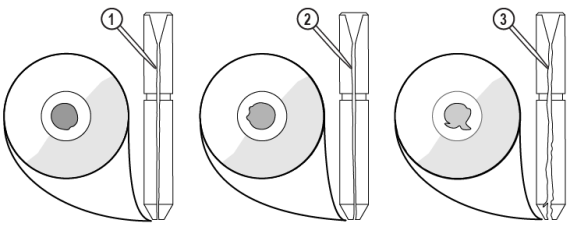
Over time, the flow of high-pressure water and abrasive wears away the inside of the mixing tube. This wear results in a gradual, irregular widening of the internal diameter of the mixing tube, causing a less accurate stream of abrasive and water. A cross-section of these mixing tubes reveals the irregular wear of their internal diameter. A cross-section of these mixing tubes reveals the irregular wear of their internal diameter. Examples of normal [1], good [2], and bad [3] mixing tube wear are shown below
The mixing tube is very brittle and easily broken if dropped or struck hard. The key to a long mixing tube life is maintaining a healthy orifice or jewel. Damage to mixing tubes caused by misaligned jets or a damaged jewel is not apparent when looking through the bore of the mixing tube. The size of the kerf and cutting performance are the best indicators of mixing tube wear. The kerf is the width of the cut made by the abrasive waterjet. With a 0.030 in. (0.762 mm) mixing tube, it can range from 0.015 in. (0.38 mm) to 0.060 in. (1.52 mm), depending on the nozzle, the thickness of the material, and the amount of wear on the mixing tube.
A clogged mixing tube is most frequently caused by using contaminated garnet abrasive. Because the opening in the mixing tube is small, even a small particle of dirt can clog it. Other potential causes of clogging include contaminated or wet garnet abrasive. Metal chips from other shop operations and paper from the garnet abrasive bag are two common sources of contamination. To clear a clogged mixing tube, see 401434-EN Operation, ProtoMAX.
Inspect the mixing tube inlet and outlet ends to see if it needs to be replaced (Figure 890). See the Maintenance Schedule for the recommended frequency for this task.
| 1. | Open the lid and lock it in the upright position. |
Use care when opening or closing the lid to avoid injury. Never let the lid free-fall. Keep hand, fingers, or body parts away from the side of the table when closing the lid.
| 2. | Place a piece of cardboard or similar material on the cutting deck to keep the mixing tube from falling in the catcher tank. |
| 3. | Remove the nozzle splash guard [1]. |
![]()
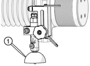
Figure 891
| 4. | Clean and inspect the splash guard for damage, replace as needed. |
| 5. | Loosen the mixing tube retainer [1] and replace or rotate the mixing tube [2] 90 degrees (one-quarter turn). |

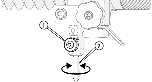
Figure 892
| 6. | Verify the mixing tube is correctly seated in the nozzle body and tighten the mixing tube retainer. |


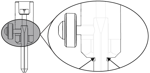
Figure 893
| 7. | Close the lid. |
| 8. | Perform a nozzle test, see Test the Nozzle. |