
________________________________________
Import, Open, or Create a Drawing File
There are three primary ways to obtain a drawing file (DXF) for ProtoMAX LAYOUT.
1. Import a drawing file from another CAD system.
2. Open a previously saved drawing file.
3. Create a new drawing file using ProtoMAX LAYOUT.
Importing Drawing Files
Importing refers to bringing a drawing that was created using another CAD program into ProtoMAX LAYOUT. Many file types can be imported into LAYOUT including .dxf, .dwg, .dwf, .ai, .pdf, and .svg (see the file formats supported list).
The LAYOUT import tool processes files received from other CAD systems through filters prior to opening as a DXF file in LAYOUT.
How to Import a Drawing File
1. In the LAYOUT main menu, click File, then select Import from Other CAD from the drop down list.
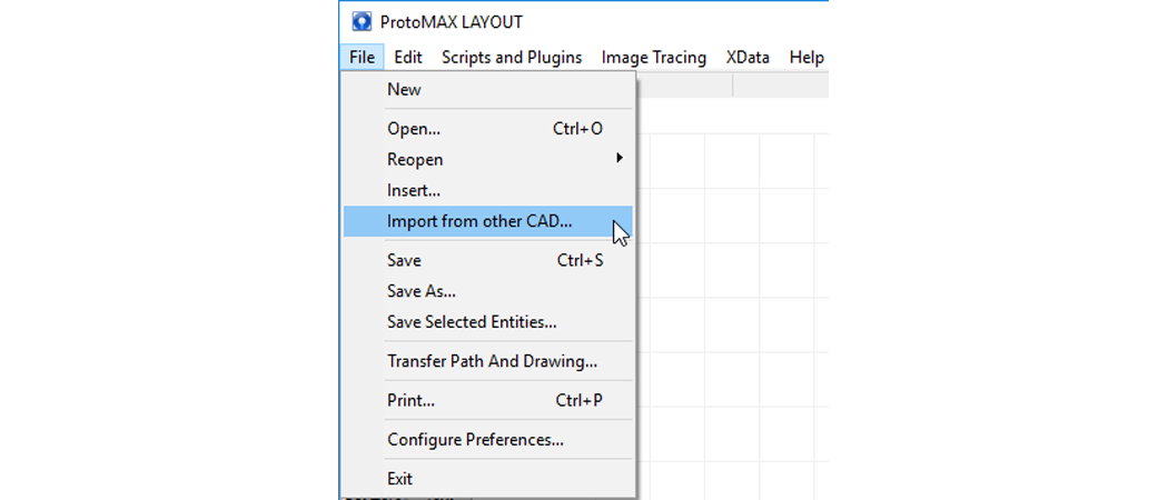
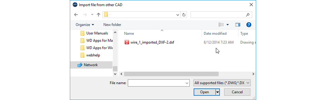
2. Select the file you want to import from the Import file from other CAD dialog box:
For more information on importing files from other CAD systems, see Import from Other CAD Programs.
Opening a Saved Drawing File
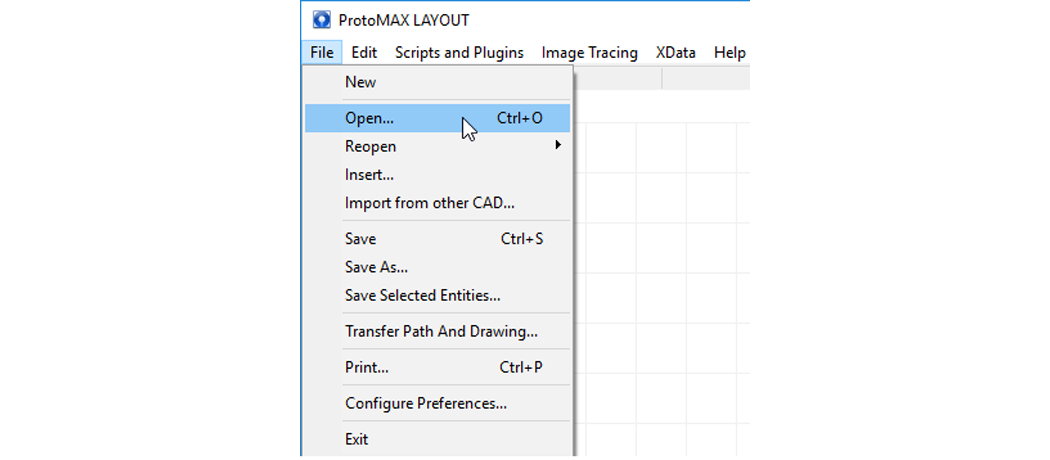
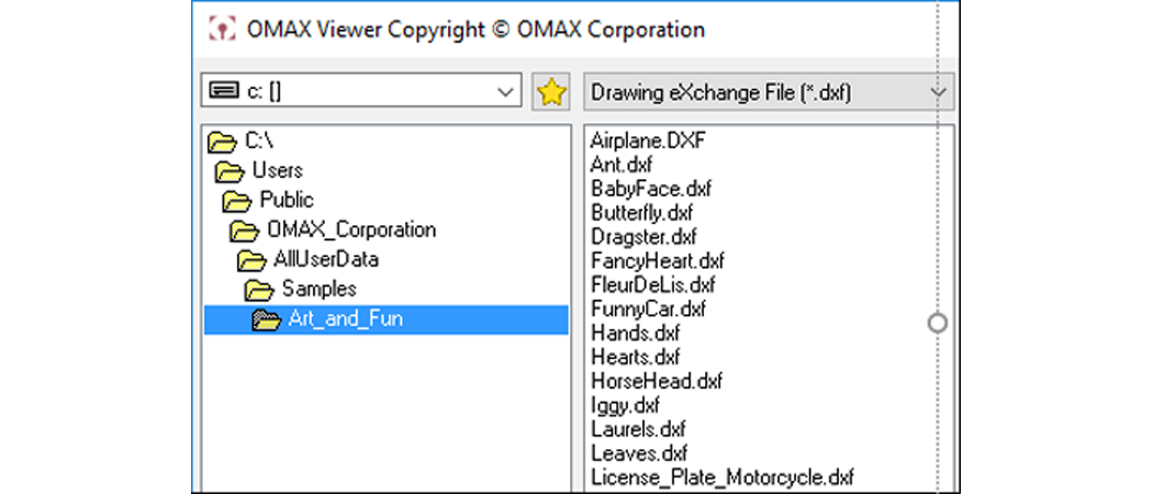
1. In LAYOUT, click File, then click Open:
2. Choose the file you want to open:
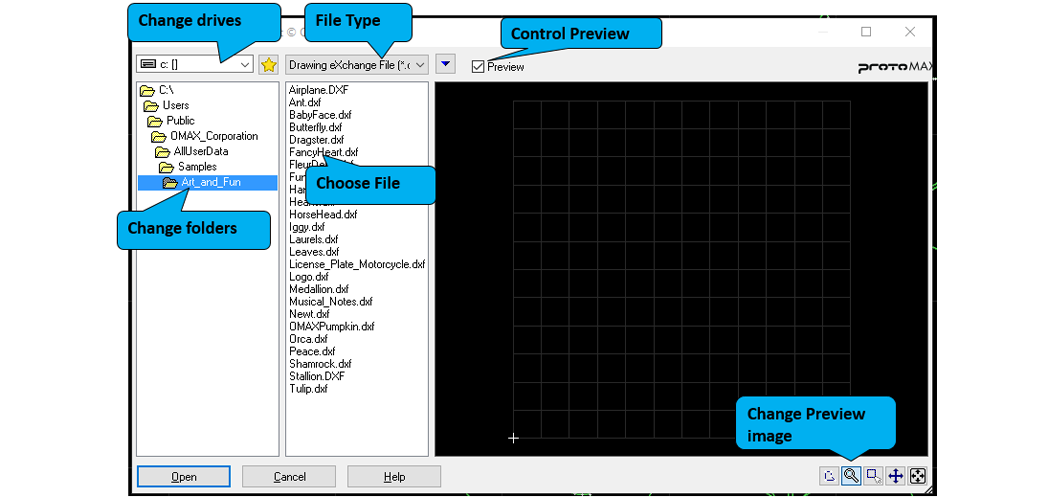
All available files can be located by accessing the following folders (Windows 10):
Creating a New File
ProtoMAX LAYOUT provides sufficient tools that allow you to create and edit your own drawing file (DXF).
How to Create a new drawing file
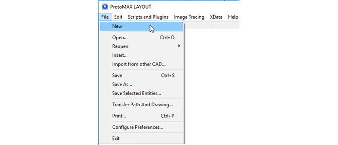
1) Click File from the main menu, then select New:
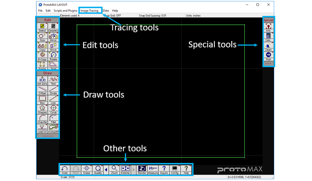
2) To start your new drawing, use these drawing tools from LAYOUT:
An example of drawing free-form using LAYOUT:
1. Click the Line tool icon to activate it.
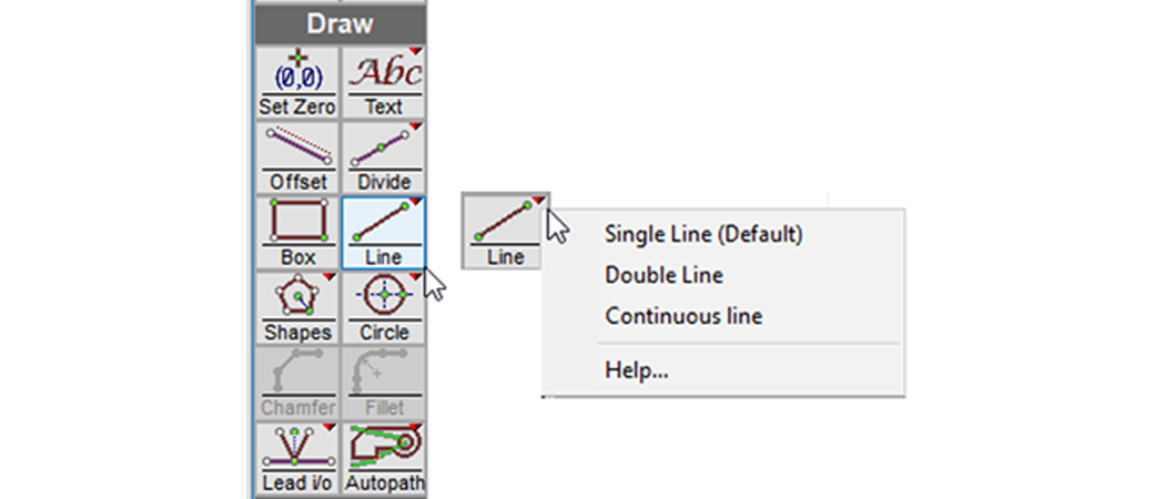
Right-click the small-red triangle on the Line icon for a list of additional tool options.
2. Move the pointer into the drawing area; the pointer changes to this graphic: +From.

3. Click a location in the drawing area where you to begin drawing your line; the pointer changes to this graphic: +To.

3) Move the pointer to the spot where you want the line to stop.
4) Click the spot on the drawing where you want the line to end.
Drawing a Line to a Specified Length
1) Click the Line tool icon to activate it.

2) Click a spot in the drawing area where you want to start drawing your line.
A Specify Dimensions dialog box opens at the bottom of the drawing area:

3) Press the Tab key, or move your pointer to either the Length or Angle box.
4) Type in your desired length and angle:

5) Press Enter or click OK to draw the specified line:

Click here to view how to draw the above line using the Specify Dimensions dialog box
Draw a Line and Connect It to Another Line Using Snap Tools
1) Click the Line tool to select it.
2) Move the pointer into the drawing area.
The Snap Tools toolbar opens up at the bottom of the drawing screen.

4. Click the applicable Snap tool to activate it.

5. Move the pointer to the geometry you want to “snap” to, and click to begin the line. The new line becomes connected to the end point of the existing line.

6. Move your pointer to the endpoint of your line, or select another Snap tool and click the geometry where you want to end the line.
Click here to view how to draw a line and connect it to another
LAYOUT Tools
Edit
The Editing panel contains tools for selecting and modifying existing part geometry. Editing tool icons contain a small “S” which indicates that you must “select” existing drawing entities before you use that particular tool.

Select
Deselect
Size
Mirror
R-Copy
Rotate
Frame
Shell
Draw
The Drawing panel contains tools for creating lines, arcs, shapes, and other part geometries. They also include tools for adding path elements to the geometry.

Set Zero
Text
Offset
Divide
Box
Line
Circle
Chamfer
Fillet
Lead i/o
AutoPath
Snap Tools
The Snap Tool ribbon contains tools used to snap to or locate specific points in drawings. It also contains access to software help, and other options that assist with working with the software.
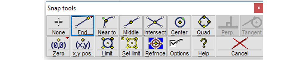
None
End
Near to
Intersect
Center
Quad
Perp.
Tangent
Zero
x.y pos.
Limit
Set limit
Refrnce
Options
Special Tools
The Special Tools ribbon contains tools that allow you to do things like access information about a drawing, access calculators, clean a drawing, and convert the drawing file to a machine tool path file.

Other Tools
The Other Tools ribbon provides tools used to assign edge qualities to your part drawing, and other tools used in editing such as the “Undo” and “Erase” tools. You can also access software help files and configure your software preferences from this toolbar.

Undo
Redo
Erase
Quality
Zoom
Extents
Render
Measure
Inquire
Config
Help