
________________________________________
Generate Tool Path
Creates the tool path (OMX file) needed to make a part

Right-click commands
The Generate Tool Path command creates the tool path as an OMX file used by the ProtoMAX to machine a part. The tool path must be one continuous path, although the abrasive jet can be turned off for parts of the path (using the traverse Quality).
After the tool path is generated, a preview of the tool path will appear. Examine the path, zooming in to ensure that the results are satisfactory. The preview can also display the kerf for the part. The tool path is not saved until you click on the Save button.
Only order each part once. If a change is made to the part, however, order the part again, or the new changes will not be incorporated when the piece is made.
Note: Before you generate the tool path, you can use the Clean command to "clean-up" the drawing. This process will detect common drawing mistakes (such as lines that are on top of each other) and correct them.
Automatically Generate Tool Path
By choosing Automatically Generate, either by selecting it from the right-click menu, or by left-clicking on the Path button, the tool path will be generated with the last set of options used in Custom tool paths. Changes to the Custom tool path options are stored and used for automatic generation.
If the custom tool path options have never been changed, the following options are used:
- The tool path is always offset to the left by the kerf amount.
- Entities with endpoints less than 1/1000th of an inch are considered connected.
- The tool path file has the same name as the part file, but with the extension (the part of the file name following the period) OMX.
- The computer will make all decisions about which direction to go when entities intersect.
If these are not the options desired for making a part, use Custom tool path options to create the tool path.
If these options are acceptable, however, quickly and easily generate the tool path simply by indicating the beginning of the path. LAYOUT will take care of the rest.
Generating the Tool Path
1. Click the Path button.
The screen changes to display the drawing full screen. A Zoom toolbar also appears.
The cursor changes to remind you to click on the start of the tool path.

The Zoom toolbar

Click on the start of the tool path
2. Click (or near) the start of the tool path. LAYOUT begins creating the tool path.
Use the Zoom toolbar to zoom in for a closer look at the point you want to use. If the part is complicated and you want to stop generating the tool path, click on the Cancel button. (With smaller tool paths, LAYOUT is usually done before you can cancel the operation.)
3. A dialog appears with the preview of the tool path.
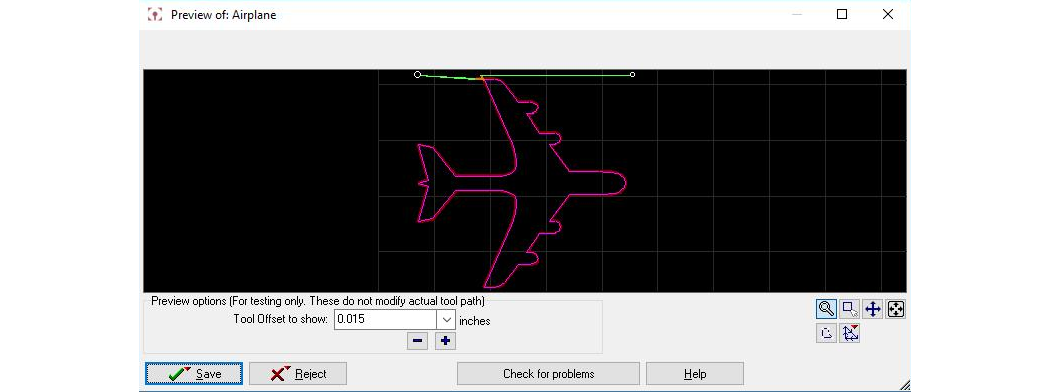
A preview of the tool path shows what the tool path will look like.
Tool Offset to show
Tool offset for the ProtoMaX is mostly fixed. It is recommend to keep it at 0.015 in. in most cases. If it is intended to send this part to an OMAX machine with a larger nozzle, it's possible to use this function to test if the path will work with that larger nozzle. Likewise, to scale the path later in MAKE (say to make the part smaller), this feature can be used to test whether a ½ scale part will still offset okay by doubling the offset seeing how it looks.
If there are inside curves that are smaller than the tool offset, an error message appears in the upper left corner of the preview dialog. The locations where problems are encountered are highlighted in yellow, to help you locate them.
Zoom tools
| Button | Description |
|---|---|

|
Draw blue arrows that show the direction of the abrasive jet machining head.
Right-click for options to control the drawing speed. |

|
Show endpoint dots in image |

|
Use Zoom Cursor in drawing (left click zooms in, right click zooms out) |

|
Zoom Window (click and drag to specify a window to zoom in on) |

|
Zoom Extents (fit all drawing elements in the preview window) |
Save Path
Save the tool path with the same name as the drawing file, assigning it an extension of OMX.

Right-click the Save button, and you can use a different name for the tool path.
After saving the file, you are returned to the main LAYOUT screen.
Reject Path
Click the Reject button, and the tool path is not saved. You return to the main LAYOUT screen.
Right-clicking on the Reject button brings up a menu with additional choices. You can choose to reject the tool path, but select those elements that made it into the path. This is useful if the tool path stopped short of including all the elements of the part. You can examine the elements that were included and figure out where the problem is (usually, either a gap in the tool path, or a poorly designed intersection).– which is typically to re-route traverses so that no traverse occurs over a previously cut feature. Or in the case of an offset error, to change the size of small inside corners to allow for the thickness of the jet.

Check for problems
Check the tool path for locations where the nozzle may move over an area where it can collide with pieces of already machined material. Areas of potential collision are highlighted in yellow. If a problem is found, re-route traverses so that no traverse occurs over a previously cut feature. Or in the case of an offset error, to change the size of small inside corners to allow for the thickness of the jet.
View Existing OMX Path

Use this option to view tool paths for drawings that already have OMX files. The OMX file must be stored in the same location as the drawing file (this is the default location when the tool path is created) and have the same name as the drawing except with the .OMX file extension.
After selecting this option, a preview dialog appears
Open OMX Path in MAKE

Use this option to open MAKE (if closed) to display the file's OMX path.
Related Topic