Offset appears on wrong side
Generate Tool Path shows the offset on the wrong side of the geometries of the part drawing
Problem
When using Generate Tool Path, the offset for certain features appears on the wrong side of the entities that were drawn for the feature.
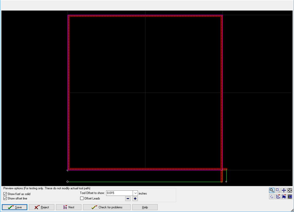
Offsets in the drawing above are being applied to the internal portion of the part rather than having the offsets to the outside of the part.
Solution
Make sure that both the AutoPath and Post utilities expect the same thing in terms of the offset sides. By default, LAYOUT offsets all entities to the left for internal features (traveling counter-clockwise) and external features (traveling clockwise). If an adjustment was made somewhere, this could be why offsets are appearing on the wrong side. This solution will be thorough enough to eliminate the issue.
- Open LAYOUT and either load a drawing or draw something from scratch (this enables AutoPath [Advanced & Configure]).
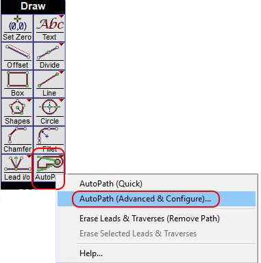
- Right-click on AutoPath and select AutoPath (Advanced & Configure).
- Click Defaults at the bottom of the dialog to change the two settings in question along with all other settings back to their respective defaults.
Alternatively, in the OMAX AutoPath dialog, make sure that the External Offsets and Internal Offsets settings apply the offset to the left. (External offsets go clockwise and internal offsets go counter-clockwise.)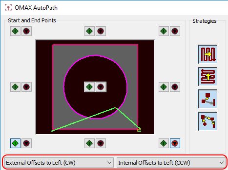
- Be sure to click OK after the setting is changed. This will save the configuration so that these settings will be used each time you click the AutoPath button.
Once the steps above are complete, if a part's toolpath geometry is created using the AutoPath utility and the toolpath file itself is created using the Post command, the tool offsets should be on the correct side of all of the features within the part.
Related topic