
________________________________________
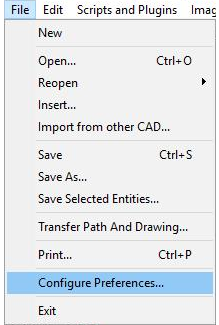
Configure Preferences
Configure Preferences sets your preferences for working with LAYOUT.
Five tabs on the Configure Preferences window are provided for setting user preferences:

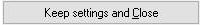
Two buttons on the Configure Preferences window save and restore settings (these buttons are visible for all tabs):
Save the settings and return to LAYOUT . The settings will be kept until you change them, even if you exit LAYOUT .
Discard all custom settings and return to defaults. (This will also discard any custom settings that may have been made earlier.)

Display
Select the Display tab to set your display preferences.
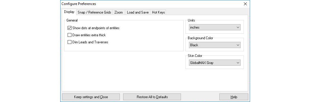
Show dots at endpoints of entities
Controls whether or not dots appear at the ends of entities (same as the Show Dots control). These points make it easier to see the endpoints of entities, which is handy when snapping to endpoints, or to get a sense of the drawing complexity.Draw lines extra thick
Controls whether entities are drawn using thick lines (same as the Thick lines control). When this is on, it will take longer each time LAYOUT redraws the part on the screen, such as when zooming or panning.Dim Leads and Traverses
When this is checked, traverse lines and lead-ins and lead-outs (lines with a Lead IO Quality) are drawn in a dimmer color. This makes it easier to see the part, especially if there are many traverse lines.Units
This list box controls the units that LAYOUT uses for drawing and reporting on entities. Changing this setting does not affect the spacing of the grid (see Snap and Reference Grids to change the grid spacing).

Choose the units you want to use
These units are used whenever LAYOUT requests a number (such as drawing a Line) or when reporting on an entity (such as from Inquire). The units used do not affect the drawing.
Background Color
Choose the color for the background of the part. The default color is Black. This has no effect whatsoever on the part, it only affects the display. Choose a color you like.
Snap / Reference Grids
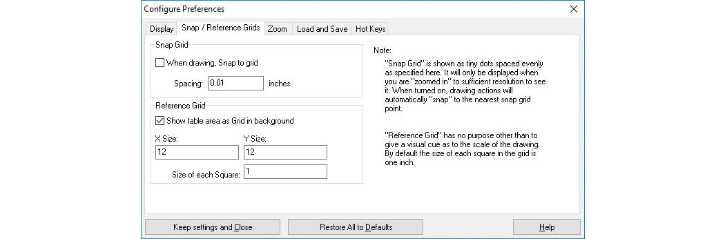
Use this page to control snap and grid settings
Select the Snap and Reference Grids tab to control the settings used for the reference grid that appears on the drawing table and the snap grid.
Snap Grid
The Snap Grid is used to make drawing parts easier. When this is turned on, lines and arcs will snap to the closest point on the snap grid. The spacing used by the snap grid can be changed. The units used for the snap grid are set on the Display page. The default setting is 1/100th of an inch.Reference Grid
The Reference Grid is the series of white lines that appear on the drawing table. The Reference Grid does not affect the part, but gives a visual reference to how large it is and can help with spacing. The X-Size and Y-Size of the grid can be set (although it is best to set them to the same size as your drawing table). The size of each square can also be set. The units used for the square size are set on the Display page.The grid is for reference only, and has absolutely zero effect on where your part will actually cut on the machine. Your part will be cut wherever the nozzle is when you click begin. The grid is there only to provide a sense of scale when drawing.
Configure Zoom
Use this page to control Zoom settings
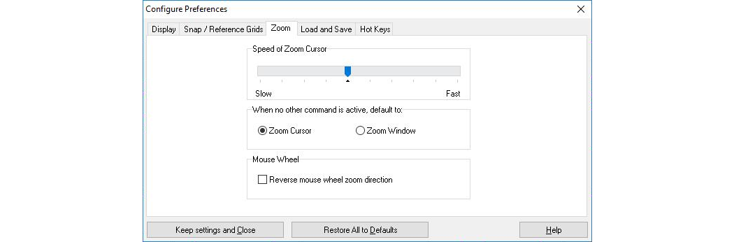
Select the Zoom tab to control settings used for the various Zoom commands.
Speed of Zoom Cursor
Although called "speed," this setting really controls how much the view changes each time you click a mouse button. When set on "slow," the view changes only slightly (zooming in, for example, might change from 133% to 144%).
To temporarily slow down the zoom function to achieve more control, hold down the SHIFT key while zooming.
When set on "fast," the view changes by a large amount (from 99% to 149% for example).
When no other command is active, default to
This controls the "default" LAYOUT command, which is usually the Zoom Cursor, but you can also choose Zoom Window. The default command is used whenever you are finished with another command.
Load and Save
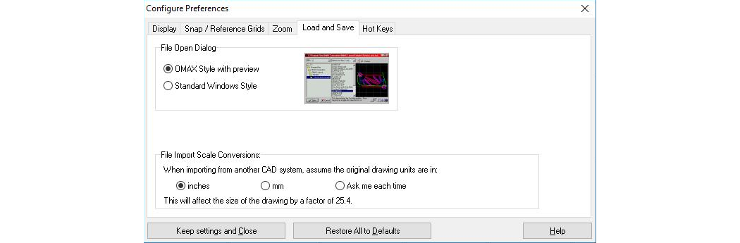
Use the Load and Save page to control what the File Open dialog looks like.
File Open Dialog
Choose to use either the OMAX Style file open dialog (which shows a preview of the drawing before you open it) or the standard Windows style file open dialog.
The style dialog is described in the Open command.
The following figure shows a typical Windows file-open dialog style. The Windows dialog is useful whenever you need a feature that is not supported by the OMAX dialog, such as the ability to sort by date, or access network folders.
When in the style dialog, the Windows style is still available as a right-click option.
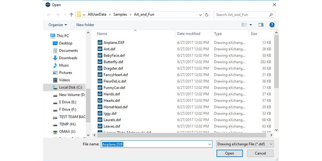
A standard Windows style file open dialog
File Import Scale Conversions
This section controls how files from other CAD systems are handled when using the Import from other CAD command. If you always work with files that are in inches, you can set this to "inches," so that no adjustment is made to the file when it is opened.
If you always import metric drawings (measurements in millimeters), you can choose "mm" so that the file will automatically be scaled down by a factor of 25.4. You can also choose "Ask me each time" to have LAYOUT prompt you each time you import a file.
This situation arises because the DXF file format is "dimensionless" (that is, there is no way to specify what dimension is used). You should always check a known dimension in the part to make sure that the size of the imported file is correct.
Hot Keys
Use this tab to assign commands to function keys
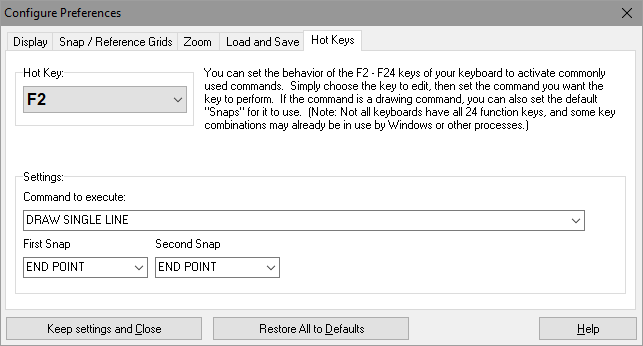
Use the Hot Keys tab to assign commands to the function keys from F1 through F24. Note that most consumer keyboards only have 12 function keys; but some industrial keyboards have the extra function keys, so this feature is provided for them.
It is also possible to reassign F1. This can be handy if this key is often pressed by mistake instead of the Esc key.
To assign a function key, or change an existing assignment:
1) Choose the function key to be assigned in the Hot Key tab.
2) Under Command to execute, select the command to be assigned to the function key. You can also use the Search Commands box to find specific commands. (For example, enter "line" to find all commands related to "line").
3) If the command is a drawing command, set the default snaps.
4) Important! Once all the function keys are set correctly, be sure to click on the Keep settings and close button. If you don't click on this button, your settings will not be saved when you close this dialog.