
________________________________________
Line
Draws a line
The mouse wheel can be used to zoom-in and zoom-out while using this command.

With the Line command, either draw a single line (by specifying two endpoints), or a series of connected lines. When drawing continuous lines, each line is a separate entity, but the end point of one line exactly overlaps the end point of the next line. You can continue to draw line segments until you press Esc.
How to Draw a Single Line
1. Click the button.
The following toolbar appears. Use these tools to specify where one end of the line will be.
You can also click the left mouse button anywhere on the drawing to specify where you want the line to start.
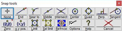
The Snaps toolbar
2. Specify the location of the ending point for the line, using the snap toolbar or the Specify Dimensions dialog.
After specifying the starting location, a light blue line will follow the cursor to indicate the size and location of the line.
The size of the line may also be entered in the Specify Dimensions dialog that appears. Enter either the length and angle of displacement, or the run and rise (slope).
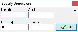
You can specify the dimensions using this dialog
By clicking on the small double-arrow button in the upper right of this dialog, the positions of Length and Angle and of the Run and Rise will be reversed. If you regularly use a CAD program that has you enter the fields in the reverse order, you can customize LAYOUT to match your other program.
You can also click the left mouse button anywhere on the drawing to specify the other end of the line. If you hold down the Shift key while you click, you will force the line to snap to the angles specified in Options.
3. The line is drawn.
The line is assigned a Quality of traverse.
How to Draw a Double Line
A double line is useful for creating a "bridge" of material to hold a section in place.
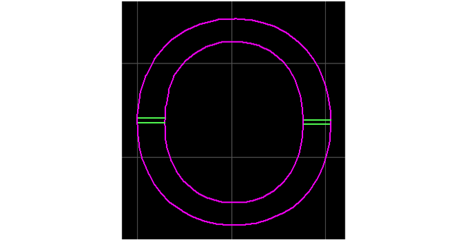
Double-lines will be used to create a bridge to hold the center
1) Right-click on the Line button.

Choose "Double Line"
2) Select "Double Line" from this menu.
The Snap toolbar appears. These tools let you specify where one end of the double line will be. You will place the center of the double-line at the selected location. If you choose the end of a single line, for example, neither of the double lines will start at the end of the single line, but will straddle it.
You can also click the left mouse button anywhere on the drawing to specify where you want the double line to start.
The Snaps toolbar
3) You can also specify the distance between the double lines using the Gap Width dialog that appears right above the Snap Tools.

Specify the distance between the lines
4) Specify the location for the ending point of the center of the double line, using the snap toolbar or the Specify Dimensions dialog.
After the starting location is specified, a set of light blue lines will follow the cursor to indicate the size and location of the double line.
The size of the double line may also be entered in the Specify Dimensions dialog that appears. Enter either the length and angle of displacement, or the run and rise (slope).

You can specify the dimensions using this dialog
Click on the small double-arrow button ( ) in the upper right of this dialog, and you will reverse the positions of Length and Angle and of the Run and Rise. If you regularly use a CAD program that has you enter the fields in the reverse order, you can customize LAYOUT to match your other program.
You can also click the left mouse button anywhere on the drawing to specify the other end of the line. If you hold down the Shift key while you click, you will force the line to snap to the angles specified in Options.
5) The double line is drawn.
See also: Offset, Shell, and Bridge.
How to Draw a Continuous Line
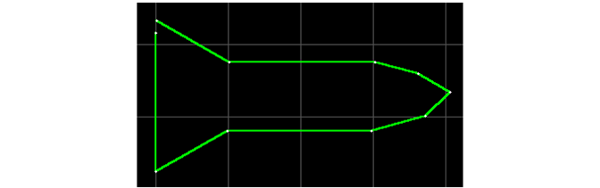
A figure drawn as a continuous Line
1. Right-click on the Line button.

Choose "Continuous line"
2. Select "Continuous line" from this menu.
The Snaps toolbar appears. These tools let you specify where one end of the line will be.
You can also click the left mouse button anywhere on the drawing to specify where you want the line to start.
The Snaps toolbar
3. Specify the location for the first ending point for the first line segment, using the snap toolbar or the Specify Dimensions dialog.
After the starting location is specified, a light blue line will follow the cursor to indicate the size and location of the line.
The size of the line may also be entered in the Specify Dimensions dialog that appears. Enter either the length and angle of displacement, or the run and rise (slope).
You can specify the dimensions using this dialog
Click on the small double-arrow button ( ) in the upper right of this dialog, and you will reverse the positions of Length and Angle and of the Run and Rise. If you regularly use a CAD program that has you enter the fields in the reverse order, you can customize LAYOUT to match your other program.
You can also click the left mouse button anywhere on the drawing to specify the other end of the line. If you hold down the Shift key while you click, you will force the line to snap to the angles specified in Options.
4. The line is drawn, and another line is started at the same location. Repeat step 2 for each line segment.
Each line segment is assigned a Quality of traverse.
5. To stop drawing lines, press Esc.
The Undo command will erase all the line segments you drew--not just the last one. If you make a mistake on a line segment, you may be better off pressing Esc and using the Erase command to erase only the segment that is wrong.
Keyboard Shortcuts
L = Single line
Shift+L = Continuous line