
________________________________________
ProtoMAX Terminology
Frosting
Kerf
Machine Tool Path
Offset
OMX File
Path Elements
Quality
Quality Tools
Sacrificial Material
Snap Tools
DXF file
Drawing files are commonly saved with the .dxf extension (Drawing eXchange File). DXF is a standard file format used to exchange files between different CAD (Computer Aided Drawing) systems. ProtoMAX LAYOUT stores all drawing files as standard DXF files.
Drawing
A drawing is a series of lines and arcs that represent something (shapes, geometry) of a part that you want to cut.

Drawing example of an airplane.DXF file
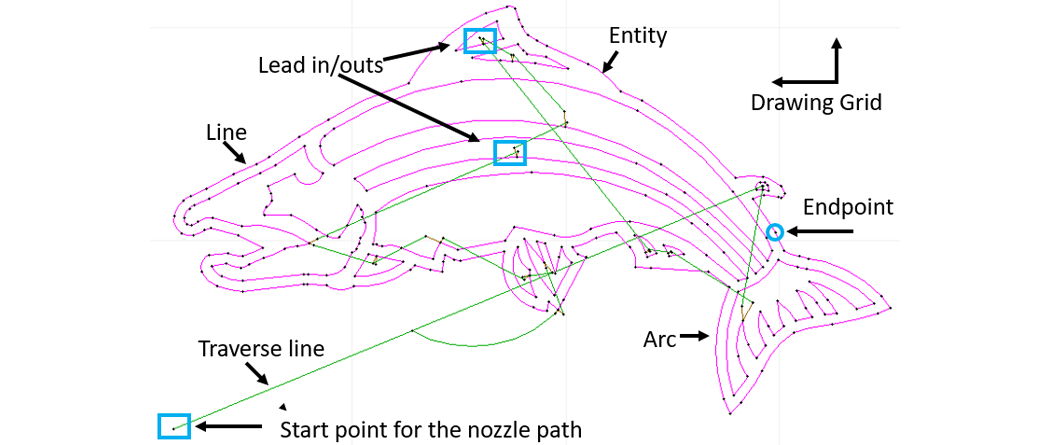
Anatomy of a ProtoMAX part drawing
Dynamic Pierce
During a dynamic pierce, the nozzle and abrasive are turned on, and the nozzle begins to slowly move. As the nozzle moves, the material is pierced.
Stationary Pierce
A stationary pierce (also called a dwell pierce) is a method of piercing the material where the jet turns on, then stays stationary until the material is pierced. This is typically a very slow method of piercing, but is fine for thin materials that pierce quickly no matter what. It also allows you to pierce the material in the minimal amount of space, and is the only option for piercing very small holes.
The hole diameter drilled using a stationary pierce will be significantly larger than the diameter of the mixing tube, especially in thicker materials. As drilling proceeds, the water and abrasive need to escape out backwards to the sides of the jet; thereby increasing the diameter of the hole.
MAKE automatically chooses between using a stationary or dynamic pierce based on the amount of room available for piercing. In the default configuration, this means that MAKE will almost always perform a dynamic pierce, unless there is not enough room. However, if stationary piercing must be used for a specialty case, then one has a few options:
Option 1: Create a small hole. For options on how to do this, see Small Holes.
Option 2: Draw very short lead ins for the part and tell MAKE in the Cutting Model Optimizations page not to grow lead ins automatically. (If you do this, be sure to set it back before cutting other paths, because it will introduce a speed penalty on all parts.)
Entity or Element
Refers to each segment within a line or arc and defined as the solid geometry between two points.
LAYOUT drawings are made up of "entities."
An entity has four parts:
• a starting point
• an ending point
• a line or arc drawn between these two points
• a cutting Quality assigned
An entity is the smallest unit used to make up drawings. There are only two basic types of entities in ProtoMAX -- lines and arcs.

A circle is made up of two arc entities

A rectangle is made up of four line entities
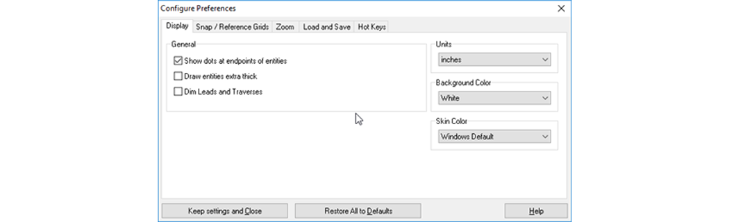
An entity is always marked at each end using a point. Entity points can be seen by selecting Show dots at endpoints of entities from the Configure Preferences drop-down window in LAYOUT:
Selected entities may be copied to the clipboard using Ctrl+C, then pasted to the drawing using Ctrl+V. This can be used to copy an object to the clipboard, load a new drawing, then paste the object into the new drawing.
Endpoint
Entities (line or arc) have two endpoints. When dots are turned on with Config Preference in LAYOUT, endpoints appear white on the screen.

Quality
Quality options control the piercing of a material and the nozzle cutting speed. Quality affects how quickly the abrasive jet head moves as it cuts a part. The slower it moves, the higher the cut quality. At the highest quality (a Quality of 5), the abrasive jet head moves its slowest.
A Quality of 1 will always pierce all the way through the material. Because the abrasive jet head is moving quickly, however, the surface finish obtained with a Quality of 1 is rougher than that obtained with a Quality of 5 (which is a smooth finish).

Quality Tools
These are Commands for setting the edge finish of entities (lines and arcs) in the drawing.

Click Quality to view the available Quality Tools
Path Elements
Path Elements consist of Lead-ins and Lead-outs, traverses, and the part geometry (lines and arcs).
Lead-ins and lead-outs are pierce entry and cut exit points.
Traverses are lines or arcs where the nozzle moves but does not cut.

OMX File
Contains data that commands the ProtoMAX machine to move the nozzle in the X and Y directions in motor-step increments. An OMX file is created from your LAYOUT drawing when you use the Generate Tool Path command. The OMX file contains your tool path (the order in which the entities in your drawing will be made).
The MAKE program uses only OMX files—it does not use the DXF file created by LAYOUT. For this reason, several OMX files may exist for the same DXF file (you might use this to make the same part in several different Qualities, for example).
Machine Tool Path
Refers to the OMX file data (the x, y motor steps) used by MAKE to machine a part. The drawing DXF file is converted to a machine OMX file using the Post tool in LAYOUT.

The LAYOUT Post tool for converting the DXF file to an OMX file
Kerf
The width of the material eroded away by the abrasive waterjet stream. The kerf normally equals the width of the mixing tube used in the nozzle assembly (e.g., 0.030 in. when using a 0.030 in. mixing tube).
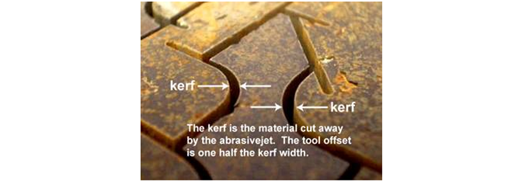
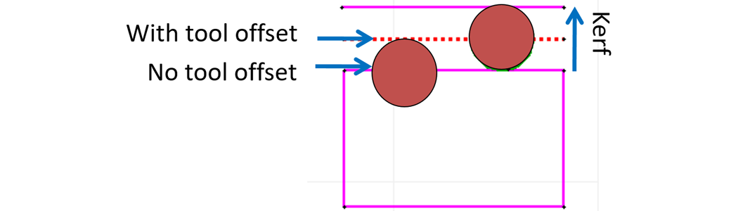
Offset
Offset is the distance the nozzle is shifted away from the geometry to compensate for the width of the jet stream. The offset normally equals half of the width of the kerf (e.g., 0.015 in. when kerf is 0.030 in.).
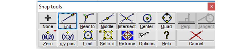
Snap Tools
Drawing tools that automatically connect geometry at some point. Used to ensure geometries are connected to specific points in a drawing

Taper
The difference in the width of the cut made by the abrasive waterjet from the top of the part to the bottom of the part. Taper is inherent in all abrasive waterjet parts.
There are many types of taper:

V-shaped taper

Reverse taper

Barrel taper

Rhombus taper
Sacrificial Material
Sacrificial material is protective material that can be sacrificed or consumed during the cutting process. Examples of sacrificial material include heavy aluminum, steel foil (or thin sheeting), vinyl tile, or other material that provides a layer of protection or stability for the part being cut.
Frosting
Frosting is the effect of stray particles abrading the surface of the material being cut. It typically occurs right at the edge the cut, on the bottom of the part sitting on a slat, or in a circular pattern around a pierce.