
________________________________________
Measuring the Abrasivejet Kerf
The kerf is the width of the material being removed as the abrasivejet cuts your part.
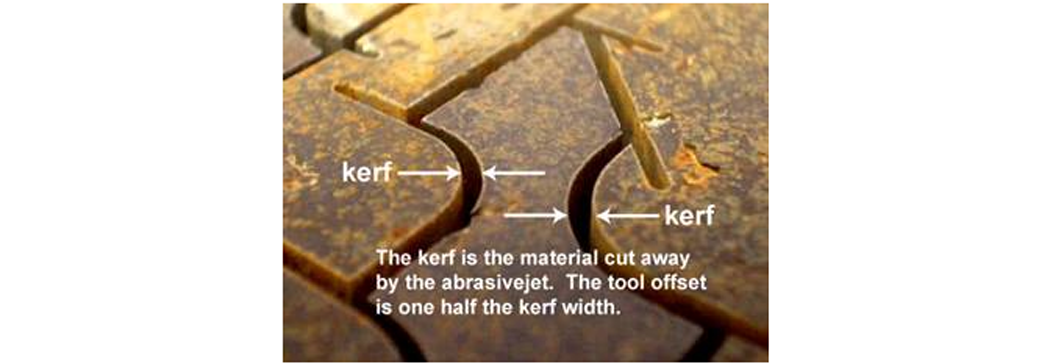
The Abrasivejet Kerf
The kerf width can range from 0.021 in. (0.01 mm) to 0.060 in. (0.15 mm), depending upon the nozzle, the thickness of the material being cut, and the amount of wear on the mixing tube. The kerf is typically measured at its widest point:

A smaller kerf width can be achieved by including any of the following factors:
- Smaller Mixing Tube
- Newer Mixing Tube
- Thinner work piece
- Lower Quality index (faster cut speed)
- Finer Abrasive (higher size mesh)
For precise cutting, it is important to know the exact width of the kerf in order to determine the correct tool offset value to be entered when configuring your material setup values.

The Kerf Width and Tool Offset Value
The offset value entered in the material setup screen for the Tool Offset should always be equal to ½ the kerf width. For a kerf width of 0.40 in. (10.2 mm), the offset entered would be 0.20 in. (5.1 mm)(1/2 x 0.40). Note: If the offset value entered is too small, then the fatter kerf will cut extra material away from your part. If the offset entered is too large, then the thinner kerf will leave excess material on the part, especially at the lead locations.
Why Measure Kerf?
Kerf width gradually increases as the mixing tube in the abrasivejet nozzle wears. An abrasive jet stream may gradually acquire an elliptical shape, which causes the tool offset to vary by a few thousandths of an inch (hundredths of a millimeter), depending upon the orientation of the stream shape to the tool path:
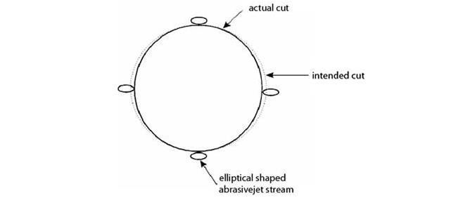
Changes in kerf width caused by an elliptical abrasivejet stream
This elliptical shape is usually due to uneven wear in the mixing tube and will tend to increase as your mixing tube wears out. This effect is not a function of the motion control equipment. Rotating your mixing tube 90° on a regular basis allows the mixing tube to wear more evenly and last longer.
The size of the kerf and cutting performance are the best indicators of mixing tube wear.
The kerf width should be frequently measured to verify accuracy of the tool offset value being used and to maintain a high degree of precision in your cut parts. You should always check tight corners, and fine details in particular, to make sure that they are not affected by the kerf. The more accurately you know the kerf (and the offset), the more accurate your cut parts will be. By adjusting the tool offset, it is possible to make parts that fit precisely together, or otherwise hold a tolerance, depending upon the quality of parts needed.
You can purposely increase or decrease the tool offset to provide extra material on the part, or to remove more material. For example, if you want to make two mating parts fit together loosely, then reduce the tool offset to have the jet cut more of the material away. Or, if you wish to leave a small amount of material to machine away later, simply increase the tool offset by the desired amount. Remember, a smaller tool offset causes the jet to be CLOSER to the part, thus removing more material. A larger tool offset moves the jet AWAY from the material; thus leaving more material behind.
If you need multiple tool offsets, for example to provide clearance in one feature and a press-fit in another, simply re-draw the features to include the dimensional change in LAYOUT. Alternatively,use the XData overrides in LAYOUT.
Cutting Test Parts to Measure Kerf
Cutting test parts and doing kerf checks on a regular basis allows you to see when cutting performance begins to degrade. If not enough material is being removed (hole too small or part too large), decrease the tool offset by half the dimensional error observed. If too much material is being removed, increase the offset by half the dimensional error. By measuring parts as they are finished, you can monitor the wear of the mixing tube and periodically reset the tool offset to achieve more precise cutting.
Make it a habit to measure and adjust your tool offset frequently, even for low precision parts. This is an opportunity to constantly practice precision, so that when precision is called for, it can be easily achieved.
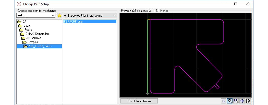
MAKE provides an DXF file, KERFCHK.OMX, located at C:\Users\Public\OMAX_Corporation\AllUserData\Samples\Kerf_Check_Parts that is useful for measuring kerf and evaluating the quality of the abrasivejet stream. This file is located as follows:
When doing a kerf check, always measure it using a test part that is cut with the same cutting Quality and material as will be used when cutting the actual part. If the part has many intricate geometries, expect that the kerf will be slightly wider. Kerf width is a function of speed: the slower the nozzle cuts (higher quality number), the wider the kerf which requires a greater tool offset. Generally speaking, using a lower speed results in a part with a better surface finish, but going too slow can also increase the kerf width and change the taper characteristics.
Taper of the kerf is controlled by two opposite trends. The jet stream loses energy as it cuts deeper into the work piece, and thus tends to form a "V"-shaped kerf. On the other hand, the natural shape of the jet is diverging, which tends to form a kerf of opposite shape. The actual kerf shape depends on the jet coherency, and the hardness and thickness of the material. The taper of the kerf is minimized by controlling (usually reducing) the cutting speed to balance these two trends. Sometimes, stand-off distance and mixing tube diameter are also used as controlling factors. In die cutting applications, taper is desirable and is achieved with the same methods.