
________________________________________
Lead i/o
Adds Lead in/out to an entity

Lead i/o right-click commands
Configure Manual Lead i/o Tool
Use The command to quickly and easily add lead-ins and lead-outs to a drawing. The "V-Style" setting adds just a lead-in and lead-out, while the "V-Style with Traverse" setting also adds a traverse to the previous lead-in/out. Typically, a "V" shaped lead provides better results than a "U" shaped lead, because the jet has less chance to "cheat" into the area where it has already cut.
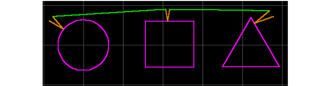
Lead-ins/outs added by the command are assigned a Quality of Lead IO, which appears brown in LAYOUT. Lead i/o Quality lets other OMAX software, such as the OMAX Nester, distinguish between the actual part geometry, and the leads and traverses.

The brown lines are the lead-in and lead-out for this circle
Adding a V-Style Lead i/o
A V-Style lead-in/out has two lines of equal length at an angle determined by the Lead i/o preferences. The lead-in/out is positioned at right angles to an existing entity. Use the following procedure to add a V-Style lead-in/out:
1) Click the button.
The cursor changes to the Lead i/o cursor.

After clicking on the Lead i/o button, the cursor changes to the Lead i/o cursor
2) Click the entity the lead-in/out will be added to.
The cursor changes to show the placement of the lead-in/out in light blue. The light blue center line is at right angles to the entity selected.
As the cursor moves, the lead i/o moves, but always stays at right angles. For example, if a circle was selected, the lead-in/out will move around the circle. If a line was chosen, the lead-in/out will move along the line (you can move past the ends of the line as well).
The red portion of the line shows the part of the lead-in/out that extends beyond the limit set in the Lead i/o preferences. If you have selected "Always create within allowed size" in the preferences, the lead-in/out will not be drawn past the blue lines. If this is deselected, however, the lead-in/out will be drawn at the size indicated by the red lines.
The center blue line is not drawn. It is used to position the lead-in/out.

The blue lines show where the lead-in/out will be positioned
3) Left-click the mouse when the lead-in/out is in the desired position.
The lead-in/out is drawn in Lead IO Quality. The tool remains in the command, and you can continue. Select the next entity to have a lead-in/out.
When done adding lead-in/outs, press to cancel the command.

The lead-in/out is drawn in Lead IO Quality
Adding a V-Style Lead i/o with Traverse
The V-Style with Traverse command adds a lead-in/out and a traverse line to the previous lead-in/out. It will only add traverse lines to the lead-in/out created immediately before. Switch to a different command, and the next time this command is used it will not add a traverse line for the first lead-in/out.
In most cases, a traverse line going from the lead-out of the previous section to the lead-in of the next section is desirable. This command makes it simple and easy to add both the lead-in/out and the traverse line.
Because this command assumes lead-in/outs will be added one right after the other, it is best to use this command after the rest of the drawing is finished. In other words, add your lead-in/outs at the end, right before you generate the tool path.
The procedure for creating a V-Style with Traverse lead-in/out is identical to the procedure for creating a regular V-style lead-in/out (except that you right-click on the Lead i/o button and select V-Style with Traverse). The first time through, the same type of lead-in/out is added.
The second lead-in/out added will draw a traverse line to the previous lead-out. Every lead-in/out added after this will be joined to the previous one with a traverse line.
Lead-in/outs added with "V-Style with Traverse" command
Switch to any other command (except using the mouse wheel to Zoom), and you will interrupt the sequence and the next lead-in/out you add will not be connected to the previous one. You can use the mouse wheel to zoom in and out while you use this command.
Configure Manual Lead i/o Tool
The Configure Manual Lead i/o Tool command lets you control the settings for both the V-Style Lead I/O and the V-Style with Traverse commands. Changes made to the preferences are retained by LAYOUT until they are changed again.
To bring up this dialog, right-click the Lead i/o button and choose Configure Manual Lead i/o Tool.
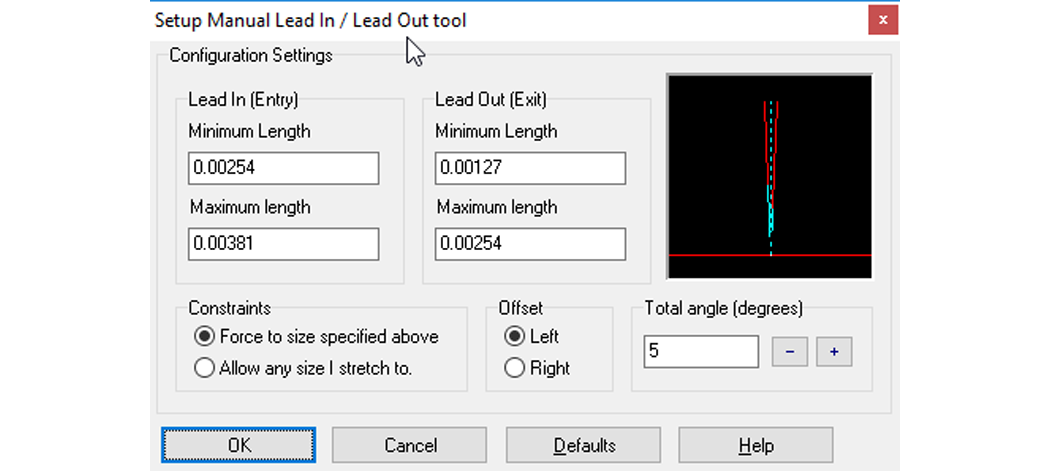
The Setup Lead i/o Tool dialog
Maximum length
The maximum length of the lead-in and lead-out. This value is only enforced when "Force to size specified above" is checked. If the lead-in/out is larger than this value, the lines turn red when positioned. The units used for this value are set in the "Display" tab of the Configure dialog. The default value is 0.5".
The values for lead-in and lead-out can be set separately. The window in the right reflects the maximum value set for the lead-ins and lead-outs.
Minimum length
The minimum length of the lead-in/out. This value is only enforced when "Always create within allowed size" is checked. The units used for this value are set in the "Display" tab of the Configure dialog. The default value is 0.15". Values shorter than this may not allow sufficient time for piercing the material. The values for lead-in and lead-out can be set separately.
Constraints
Always create within allowed size or Allow any size I stretch to
When "Force to size…" is selected, the lead-in/out is always created greater than the minimum size and less than the maximum size, regardless of the length requested. If the length is between the maximum and minimum, the requested length is provided. The light blue lines will always show the length of the lead-in/out when this is checked.
If "Allow any size…" is selected, the lead-in/out is drawn at the specified size, even if it is ridiculously large or small. With this option selected, both the lead-in and the lead-out are the same length. When the lead-in/out is created, the display will show the minimum and maximum lengths that were specified to help guide you, but you can make them shorter or longer as desired.
Offset
Left or Right
This affects how the traverse is created when using the V-Style with Traverse command. When Left is selected, the lead-in will be positioned to allow the offset to be on the left of the tool path (in the window, the lead-in is shown on the left). If the tool path is to be offset on the right, the lead-in and lead-out positions are reversed.
Total Angle
The angle in degrees between the lines of the lead-in/out. Either type in an angle directly, or use the + and - buttons to adjust the value of the angle. The window above this setting changes to reflect the current value.