
Create Tab
Adds a tab to a drawing

If you use this tool, be aware that the AutoPath command supports parts that contain tabs.
Keyboard Shortcuts
Ctrl+T - Add tab
A "tab" is a small piece of material that connects your part to the main sheet of material. Tabs are used with thin materials, both because a tab in thick material can be difficult to break, and because thin materials tend to have more problems with parts floating in the tank.
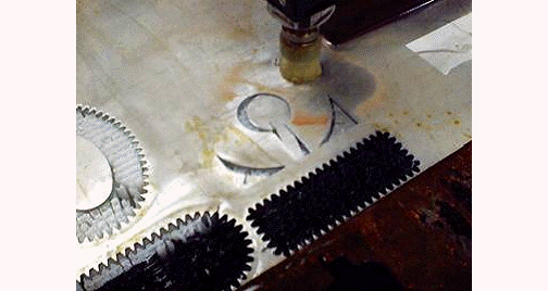
For this part, a tab should have been used to keep the scrap from slipping under the material.
The command is fairly automatic - just click where you want the tab to be. You can also "fine-tune" the settings so that you can get exactly the type of tab you want.
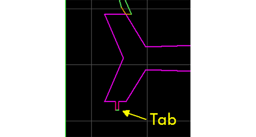
A tab added to the airplane part
How to Add a Tab
1. Right-click the button and choose from the menu. You can also type Ctrl+T.
Right-click to display this menu
2. The Tab Tools button appears and the cursor changes to the tab cursor .


Tab Tools dialog
Use of the Tab Tools Options button in accessing the Tab Setup dialog is explained in detail below.
3. Click where you want to create the tab.
The tab appears at the closest entity to where you clicked and on the same side you clicked.
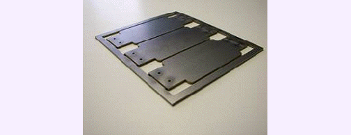
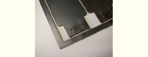
Part held in place by tabs
A simple alternative to cutting tabs is to end the cutting path just prior to finishing the cut. This is done without using the Create Tab tool and can give the same or better results.
Tab Setup Dialog
To access the Tab Setup dialog:
1) Right-click the button. Select Create Tab to display the Tab Tools dialog box.
2) Click the button to display the Tab Setup dialog.
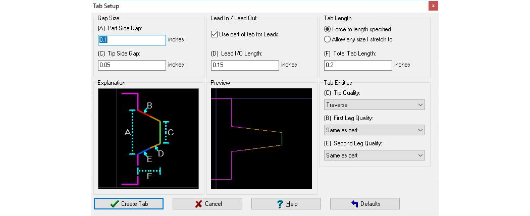
The Tab Setup dialog
• Part Side Gap
The width of the tab at the part measured in the current units.• Tip Side Gap
The width of the tab at the Tip measured in the current units.• Lead In / Lead Out
To achieve a smoother start and stop of the cuts, you can specify to use Leads on the end of the Tab legs.
NOTE: The Lead length may be adjusted in MAKE depending on settings that control Leads growing and shrinking.
• Tab Length
The length of the tab measured in the current units.
If "Use part of tab for Leads" is checked, the Leg Length includes the Lead length, so it can't be shorter than the Lead length.• Tab Entities
The cutting Quality used for the legs (the outside of the tab). Generally, you'll want to use a Quality that cuts through the material, but you don't need a high finish, since the tab will be removed. The "first" leg is based on which leg LAYOUT determines is cut first. Each leg can have a different Quality.
Typically the Tip will be a Traverse quality, but it can be cut quality• Tip Quality
The cutting Quality to use at the tip of the tab. Be sure to use a Quality that doesn't cut through the material. The default is "Traverse" (no cutting).
If you want to use the tab as the beginning and end of the tool path, you can choose "None" for the tip quality. This creates the legs of the tab, but does not draw the tip line.• Preview
The Preview illustrates approximately what the tab will look like (except length when "Allow any size | stretch to" is checked).
As you drag the cursor around before clicking the mouse to set a tab, notice that the Tab will "snap" when you get close to a corner. This helps avoid creating very small entities which can have a big effect on the speed of a cut.
Tabs can be angled or straight. The angle can be toward or away from the part, depending on your needs!See Also
Configure Manual Lead i/o Tool