
________________________________________
Assigning Cut Qualities
Why assign a cut quality?
Cut Qualities tell the nozzle how fast or slow to move to achieve a certain edge finish on your part.
Faster – rougher part edge
Slower – smoother part edge
Available Qualities Toolbar
Click the Q/Quality icon to select the Available Qualities toolbar.

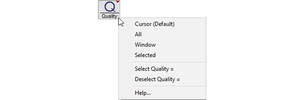
Or right-click the Quality icon to see more options.
Traverse Icon
- Uses a solid green line
- Moves the nozzle without cutting
- Uses no water, nor abrasive
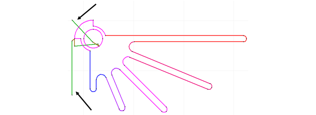
- Assigns different colors for different qualities
- Number and color on the toolbar corresponds to colored entities in the part
- Higher number = higher quality
- Lower number = lower quality
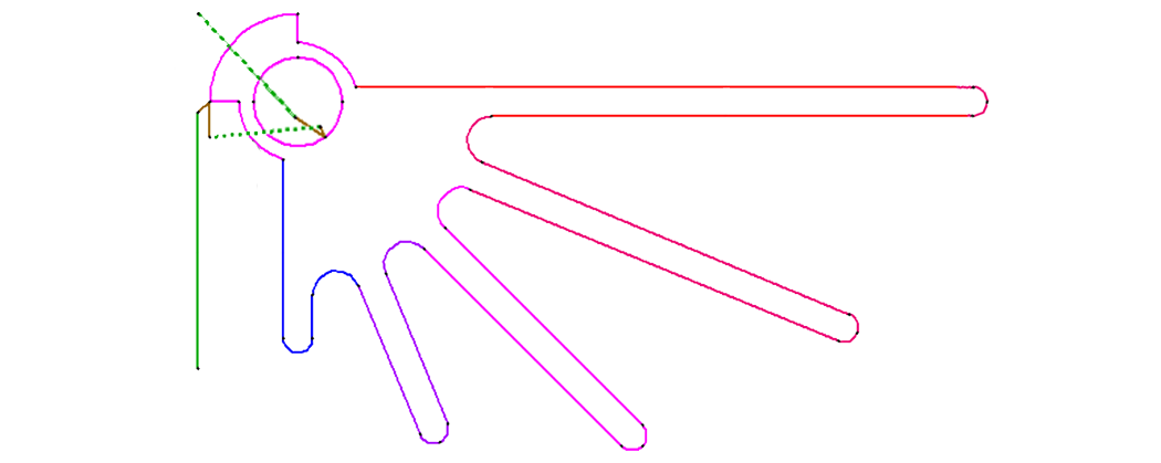
Lead In and Lead Outs
- Drawn in brown
- Lead ins (usually drawn longer) use water and abrasive to pierce the material before cutting
- Lead outs (usually drawn shorter) allow the jet stream to catch up and finish the cut before turning off the water and abrasive

How to Assign Qualities
1. Open a drawing in LAYOUT.
2. Click the Quality icon to display the Quality tool bar (or right-click the Quality icon for more options).
3. Select the number you want.
4. Select an entity on the drawing to be assigned your chosen quality.
Assigning Qualities Demonstration
1. Draw a box with 2 circles in it using the drawing tools.

Click here to see how to draw the above box using the ProtoMAX Draw Tools
2. Assign each entity a different cut quality using the Quality tool bar.

3. Use other methods to assign qualities.
a. Right-click the Quality icon.
b. Use keyboard shortcuts such as:
• Q for Quality (type the Quality number you want – for example, Q3 for quality 3)
• QA for Quality All
• QW for Quality Window