
________________________________________
Render in LAYOUT as Solid
Use Rendering to create a more accurate representation of the final part from a drawing composed of simple lines and arcs
Reasons for Rendering
- Makes it easier to see what is scrap and what is part when developing the drawing or tool path
- Finds mistakes in the drawing or tool path
- Creates an image to insert into an email, quote, or other document

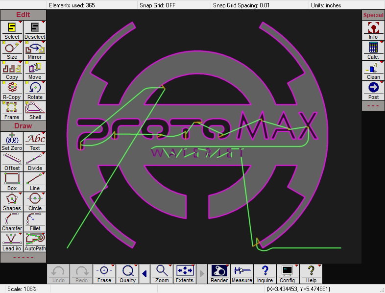
Example of rendering in LAYOUT as a solid.
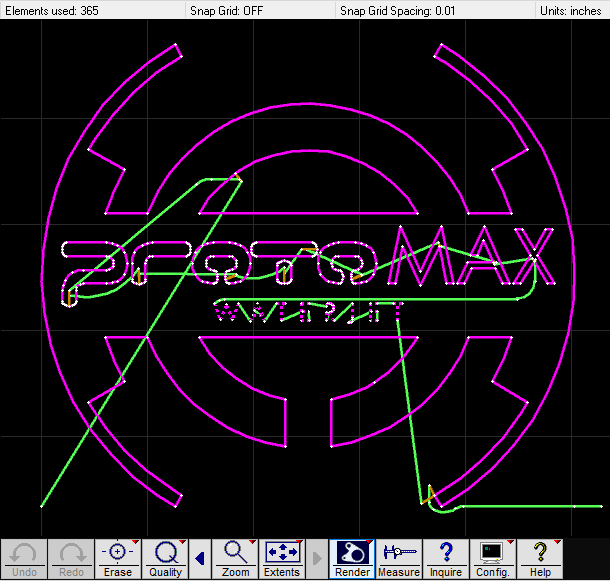
Example of rendering in LAYOUT as a solid with entities.
There are multiple spots in LAYOUT where it is possible to "render". This help page refers to rendering from within the main LAYOUT screen. It is also possible to render the final tool path, which is a different topic. See also: Render Tool Path as Solid.
Rendering draws temporarily to the screen. Subsequent screen redraws will clear the rendering. It is possible to render to the Windows clipboard by either right-clicking the Render button and choosing Render to Windows Clipboard, or holding down the SHIFT key at the very start of rendering. It is also possible to render to a .jpg file by right-clicking the Render button and choosing Render to file.
Rendering is not perfect and follows some rules to do the best it can:
- For the Render in LAYOUT as Solid command to work, one must first have something drawn that is reasonable to expect to cut on a machine. That means, that Qualities should be assigned, and the part must have continuously connected features to define it. (Most of the ProtoMAX sample files meet these criteria.)
- While working in the main editor in LAYOUT , the software does not "know" anything about your part, sequence of cutting, etc., beyond the lines and arcs and qualities that you are working with. Because of this, it can only make a best guess as to what the final intention of your part and path may be. For this reason, rendering is not possible for every possible cut. The software has to make some assumptions about what features define the part, what features define the scrap, what features define slits, etches, and so-on. Sometimes it will make the wrong assumptions, and the render will not look as you expect. In this case, it is advised to either not use rendering, or to find some alternate method such as 3rd party software to do what you need. Rendering works best for 2D parts that are typical of what most people cut on their machines most of the time.
Some things that will confuse the rendering process:
- No cutting entities assigned (the rendering process ignores traverses)
- Entities that have nothing to do with the final part (for example construction entities, unless they are drawn in green, which will just be ignored.)
- 3D features such as secondary cuts to make compound bevels
- Tabs and gaps (which will render, but will not consider the part to be anything different than the scrap around it, as though you are simply cutting a slot.)
- If Rendering does not provide the results you expect, consider also that there may be that the rendering algorithm was simply unable to resolve the data, but also consider it may indicate a problem with your part drawing, such as a gap in a feature, duplicate entities that need "cleaning" or similar.
Rendering Options
To render a drawing, either click the Render button at the bottom of LAYOUT , or press CTRL+R.
The location of the Render button in LAYOUT
Right-clicking the Render button provides additional options.

The Render button right-click options
Click Render (Default) to create a solid rendering of the current drawing:

A rendering example with Render (Default) selected.
Select Render with Entities... to create a solid rendering of the current drawing that also includes all entities:

A rendering example with Render with Entities selected.
Select to store the current render in the Windows clipboard.
Select to save the current render as a .jpg file.
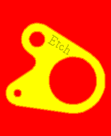
Select to display the Setup for Default Rendering window allowing you to select custom foreground and background colors for your rendered drawings:

The Setup for Default Rendering window

A rendered drawing example with custom colors
Clicking the  button reverses the foreground and background colors for the rendered drawing being displayed.

Tips:
- Rendering of giant drawings can be slow. Press Esc to cancel.
- If what you really want is simply a screen-shot, press ALT + Print Screen to copy a screen shot of whatever window is active to the Windows clipboard. (This is a feature of Windows, not ProtoMAX software, so can be used for most any screen capture needed.)