
________________________________________
Chamfer
Creates a beveled edge between two entities
The Chamfer command (pronounced "cham(p)-fer") creates a beveled edge between two entities and is typically used to add a finished appearance to a part and to remove sharp edges.

The two lines on the right have a 0.25" Length Chamfer applied.
Chamfer is selected by right clicking the Chamfer button.

Chamfer Tabs
Trim affected entities
When checked, the "leftover" entities (the parts that extend past the chamfer) are removed. In most cases this is desirable. When unchecked, the lines are divided at the join point but are left untrimmed.
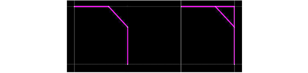
The entity on the right is not trimmed; the left one is.
By Distance
The By Distance tab....

• D1 is the length of the leg from the intersection point of the first clicked entity at which to divide.
• D2 is the length of the leg from the intersection point of the second clicked entity at which to divide.
• Select the lock (add image) check box to lock D2 to the same value as D1.
• Auto Distance allows LAYOUT to determine the distance from the intersection where it will divide. The new entity will be placed from the nearest point to the click of each entity.
See Trim affected entities above.
The Distance Chamfer is the only chamfer mode that supports arcs.
By Length
The By Length tab....

L is the length of the resulting entity.
See Trim affected entities above.
By Angle
The By Angle tab....

L is the length of the resulting entity
A is the angle in degrees to the first clicked entity that the resulting entity should be rotated. On two entities intersecting at 90 deg, an A of 45 and a L of 1 would have the same result as "By Length" with a L of 1.
How to use the Chamfer Command
1. Right click the Fillet button to display the Chamfer dialog.
The Chamfer dialog
2. Select a Chamfer type by clicking the corresponding tab.
3. Click the first entity to chamfer. The entity is highlighted in blue
4. Click the second entity to chamfer.
5. The selected chamfer type is added.
If the two entities do not intersect, the Chamfer command extends the entities and chamfer from the intersection point.
If the two entities have different qualities, the quality of the first entity clicked is used for the chamfer.
The Chamfer command will remain active, allowing additional chamfers to be added. When finished, press Esc to return to the default Zoom command.
• Just like the Fillet tool you can enter "0" for the Length or Distance to join two disconnected entities or remove gaps in corners.
• Just like the Fillet tool you can press the "T" key to enable or disable the "Trim affected entities" option.
• Also Just like the Fillet tool you can press the "A" key to switch to "Auto Distance" mode. "Auto Distance" is only available in Distance mode. If you are not in Distance mode you will be switched to the appropriate tab when "A" is pressed.
Each chamfer is stored separately in the Undo list, allowing you to undo each one individually.