
________________________________________
Create the Drawing Path
A drawing map determines the path the ProtoMAX nozzle follows when cutting your part. The drawing map adds a few more pieces of geometry to your drawing file such as traverses, Lead-ins, and Lead-outs.
The nozzle always follows a traverse path when not cutting. Lead-in and Lead-out paths define where the nozzle pierces and where it exits the material being cut.
Traverses and lead-in/outs can be added to your drawing file using the Automatic Path tool.
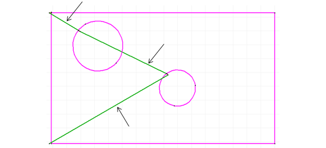
Traverses:
• Can move the nozzle without turning on the water and/or abrasive
• Can be lines or arcs
• Are colored green (solid or dashed)
• Typically are connect to lead in/outs
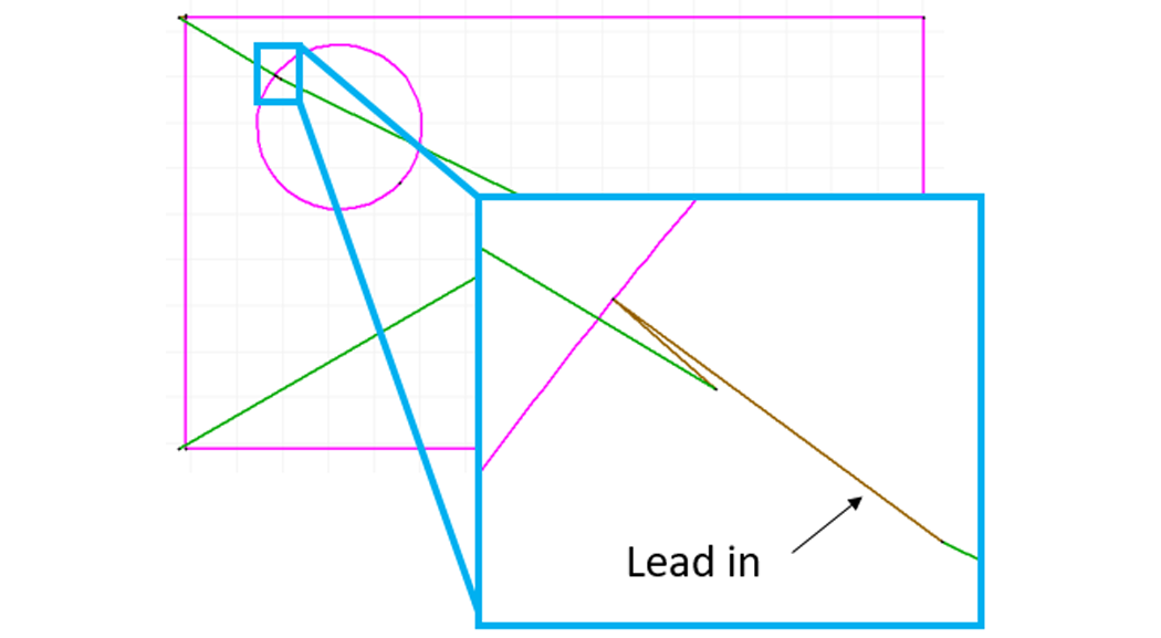
• Turn on water and abrasive, pierce the material
• Are used as piercing points
• Color - Brown
• Typically drawn longer than lead-outs
• Connect to lead-outs
• Determine nozzle travel direction
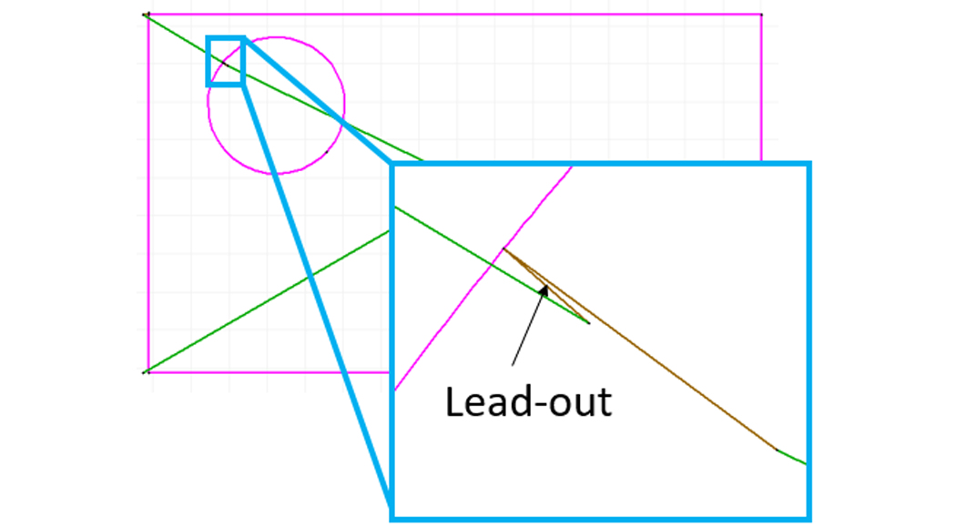
Lead-outs
• Exit points
• Turns off the water and abrasive and proceeds to the next command
• Color - Brown
• Typically drawn shorter than lead-ins
• Connected to lead-ins
Create a Tab
A tab can be added to an existing drawing by using the Create Tab command:
1. Right-click the Lead i/o icon:

2. Select Create Tab:

3. Refer to Create Tab in the help files for tab creation instructions.