 Install the ProtoMAX
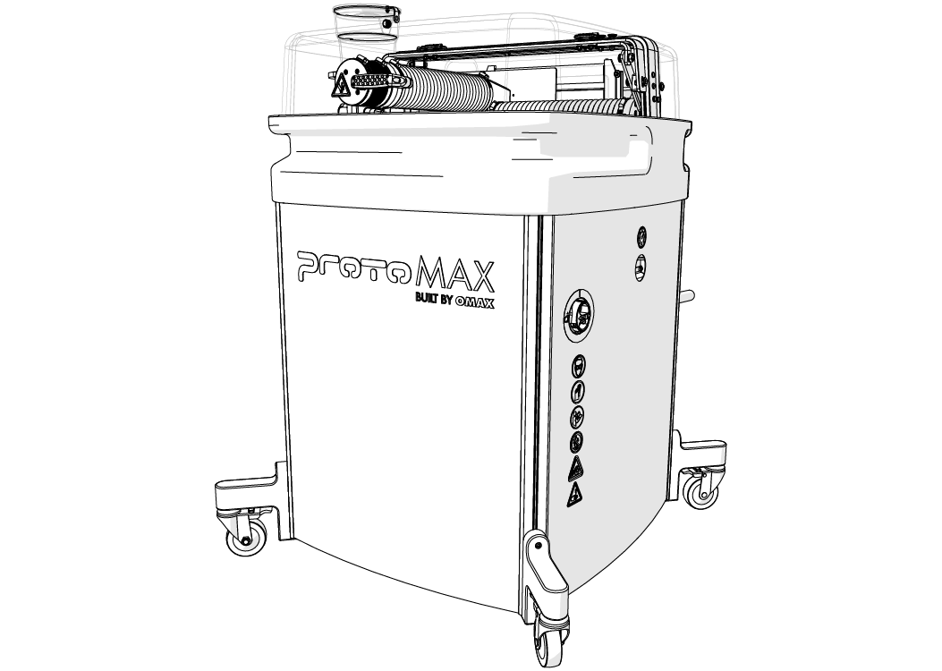
Hypertherm, Inc.
21409 72nd Avenue South
Kent, WA USA 98032
Information:
Technical Support:
E-Mail:
Web:
This document contains subject matter to which Hypertherm, Inc. has proprietary rights. Recipients of this document shall not duplicate, use, or disclose information contained herein, in whole or in part, for any use other than the purpose for which this manual was provided.
Hypertherm, Inc. believes the information described in this manual is accurate and reliable. From time to time, design improvements will be made to the OMAX equipment. Photographs, text, and sketches within the body of this manual may not exactly represent your equipment. In general, this manual contains the most up-to-date information available. However, Hypertherm, Inc. cannot accept any responsibility, financial or otherwise, for any consequences arising out of the use of this material. The information contained herein is subject to change, and revisions may be issued to advise of such changes or additions. OMAX strives to continually improve user documentation. If you have any questions or concerns about the content of this user’s guide, please e-mail us at tech_writing@omax.com, or write to us at:
Hypertherm, Inc.
Technical Publications
21409 72nd Avenue South
Kent, WA, USA 98032
Hypertherm, Inc. is continually improving their equipment to bring you the best in abrasive waterjet machining technology. For that reason, your abrasive waterjet may differ slightly from what is described in this document. If you have any questions, please feel free to speak to us at 1-818-647-1994 or e-mail us at info@protomax.com. You can also receive technical support on-line at: Web: www.omax.com.
Important Safety Information
SAFETY IS YOUR RESPONSIBILITY.
For your own safety, read this guide thoroughly and carefully before the equipment is installed, operated, maintained, or issues are troubleshooted.
Save these instructions.
This guide contains important safety information for the equipment. Careful compliance with the safety information helps prevent physical injury, damage to the equipment, and can extend the equipment's life.
Equipment safety features, safety glasses, hearing protection, and more can reduce potential injury. Be careful when the equipment is installed, operated, and maintained. Safety guards and features do not guarantee your safety if you are careless, inattentive, or use poor judgment. If it feels dangerous, do not try it.
YOU ARE RESPONSIBLE FOR YOUR SAFETY IN YOUR SHOP.
Machine Safety Labels
These safety labels can appear on the equipment. If ignored, physical injury, death, or equipment damage may occur. Read the complete safety information in the operation, installation, or maintenance guide before the equipment is installed, operated, or maintained.

WARNING Electrical Shock
Dangerous voltages. Do not access areas with this label before the applicable safety precautions are done; lockout/tagout the power and make sure there is no voltage on the circuits before installation, maintenance, or other work is done.

WARNING Airborne Debris
Eye protection and hearing protection are required during operation. Do not remove the abrasive feed tube from the nozzle or hopper when pressurized. The pressure can blow abrasive into the air, and the abrasive particles can get into the eyes and contaminate tools and machines.

WARNING Keep Fingers and Hands Away From Parts that Move
Keep hands and fingers away from the machine when it moves and during operation. Fingers and hands can be crushed and cut by machine parts when they move. Do not try to gain access to the machine or parts during operation.

WARNING Pinch Risk
Keep hands away from the edge of the catcher tank when the lid is closed.

WARNING Keep Hands Away From Jet
Do not put hands or fingers near the nozzle during operation. Immediately get medical aid for abrasive waterjet injuries. Injuries caused by high-pressure abrasive waterjet systems are dangerous. Do not wait to get medical aid!

WARNING Watch Hands and Fingers
Always keep the motor guards in position during operation. Keep hands away from belts and pulleys during maintenance and service.

Electrostatic Discharge
Attention! Be careful when electrostatic-sensitive devices are touched. Use electrostatic discharge protection procedures.

No Open Flame
Do not smoke near the equipment. Do not operate the equipment in an explosive atmosphere. Make sure ignition sources (such as flames or electrostatic discharge) are not near the equipment. Do not store flammable materials near the equipment. Do not use equipment in or around flammable gases or liquids. Do not let explosive or flammable vapors collect in the area around the equipment. Make sure there is good airflow in the work area to dissipate gases, vapors, and fumes. Be especially careful when machining materials that create sparks, such as titanium, which can cause gases in the catcher tank to explode.

Do Not Operate With Guard Removed
Do not operate when the guards or panels are removed.

Do Not Spray
Do not spray water on or near the machine's electrical enclosure.

Do Not Step
Do not step, stand, or walk on the slats. The slats can become weak after operations and can fall under more weight.

Read Manual First/Do Not Adjust
Do not adjust. Read the manual. Special instructions could be required before adjustments are made. Adjustments to the equipment can have unwanted effects and cause injury or damage.

MANDATORY ACTION Disconnect Power
Always disconnect the primary power cord from the electrical source to isolate the machine from its electrical supply.

Read Manual
Read the equipment operation guide for important safety information and operation instructions. Do not operate this machine until all safety precautions and operation instructions are read and understood.

Wear Hearing Protection
Always wear hearing protection when near the equipment during operation. When operated above water, noise levels can exceed 70 dBA.

Wear Eye Protection
Always wear approved safety glasses when the abrasive waterjet system is operated. Other types of glasses do not give sufficient eye protection! The garnet abrasive is not a chemical irritant, but garnet can cause an eye injury like sand if it is not quickly flushed. Also, the catcher tank water can contain particles from the material or other chemical irritants. Have an eye-wash station near the work area if the abrasive spray gets into the eyes.
Read the product labels and refer to product Safety Data Sheets (SDS) to identify the properties and risks of chemical products and materials referenced in this document. Use good industrial hygiene, safety practices, and personal protective equipment identified in the SDS.

Wear Gloves
The catcher tank water can have dangerous bacteria in it. A small break in the skin can introduce the dangerous bacteria into a wound. Always wear protective gloves if there are cuts or wounds on the hands or fingers. When material is put on or removed from the slat bed, wear gloves that give protection against sharp metal edges.
Read the product labels and refer to product Safety Data Sheets (SDS) to identify the properties and risks of chemical products and materials referenced in this document. Use good industrial hygiene and safety practices. Use personal protective equipment as specified in the SDS.
Safety Precautions
Safety instructions must be followed when the equipment is installed, operated, or maintained. If ignored, death or physical injury can result, or damage can occur to the equipment. Always follow the applicable safety precautions when work is done with this equipment.
Use the equipment ONLY for its intended function
- Read the installation manual before the equipment is set up to learn about important installation and safety information.
- Read the documentation for recommended accessories. The use of incorrect accessories can cause a risk of injury to persons or damage to equipment.
- Wear eye and hearing protection. Always wear ISO-approved impact safety glasses.
- Make sure the equipment is installed correctly before the system is started.
- Never stand on the equipment. Serious injury can occur if the machine tips or you touch the machining tool during operation.
Do not make changes
- Do not make changes to the equipment or components that are not approved.
- Changes to the equipment can cause a risk of physical injury to the operator and others and can cause damage to the equipment or other property. Changes to the equipment will void the warranty.
- Do not change, defeat, or bypass the equipment safety features.
Do not remove panels
- Do not remove the panels during operation. Only remove them when required by maintenance or to troubleshoot problems.
Check for damaged parts
- Before the equipment is used, carefully examine guards or other parts that are damaged to make sure that it operates correctly and functions as intended. Examine to make sure parts that move, move freely, are aligned correctly, are not broken, are mounted correctly, and for other conditions that can have an effect on its operation. Replace guards or other damaged parts.
Use caution, stay alert, and be attentive
- Do not install, operate, or service the equipment while under the influence of alcohol or drugs. Read the warning labels on prescription and over-the-counter drugs. If in doubt, do not install or operate the machine.
- Do not install, operate, or service the equipment when you are tired.
- Always follow the safety precautions when the equipment is installed, operated, maintained, or serviced. Carefully operated, the abrasive waterjet is a safe tool. When operated carelessly, serious injury can result.
- Wear a face or dust mask.
- Do not reach over the machine to operate it. Keep feet on the floor and balanced at all times.
- Keep a minimum of 16 in. (40 cm) away from pressurized equipment during operation.
- Do not try to tighten the ultra high-pressure (UHP) fittings when the system is pressurized.
Keep the tools and equipment in good condition
- Keep machine and accessories clean for the best and safest performance.
- Always keep the equipment in good condition.
- Follow the maintenance instructions for equipment and accessories.
- Keep all protective guards and stop devices.
Keep the equipment and area around the equipment clean and free from clutter
- Remove all installation, operation, or maintenance tools from the equipment before it is operated.
- Keep the work area clean and clutter-free to prevent accidents.
- Keep the equipment clean for the best performance.
Do not operate the equipment in a dangerous environment
- Do not use the equipment in or around flammable gases or liquids.
- Do not expose the equipment to rain or use it outdoors.
- Keep the equipment in a bright work area.
Never leave the equipment unattended during operation
- Always stop and turn off the equipment before leaving the area.
- Keep visitors at a safe distance from the work area.
- Keep children away from the equipment work area.
- Do not let children play around or operate the equipment or its components.
Never operate the equipment without safety guards or covers
- Do not change, bypass, or try to defeat the safety guards, covers, or switches.
- Keep the guards in position and in working order.
- Do not remove the safety cover or guard during operation.
- Know the location of the ON/OFF switch.
- Know how to disconnect the primary power supply to the equipment.
- Start and operate the machine only when all side panels are in position.
Never put your hands in the area of the nozzle during operation
- Seek immediate medical aid for all waterjet injuries. Injuries caused by high-pressure abrasive waterjets are serious. Do not wait!
- Refer to the WaterJet Technology Association (WJTA) warning card for important medical aid information.

Figure 55
Be careful when material(s) is moved in the catcher tank
- Do not operate the equipment when material is moved into the catcher tank.
- Always stop the abrasive waterjet before adjustments are made to the material or the abrasive jet.
- Always be careful when material is moved into the catcher tank. Fingers can be caught between a heavy part and the support slats.
- Be careful around the support slats. The abrasive waterjet also cuts the support slats; the edges can become sharp and cause cuts or collapse.
Do not touch live electrical components or parts
- Always use a licensed electrician or approved person to install the primary power source to use with the machine.
- Examine the equipment power and control cables regularly for correct connection and installation. Damaged, exposed, and bare wires can cause electrocution or death!
- Make sure the equipment is correctly connected and grounded in accordance with the national, state, and local codes. Do not remove the prongs from the plug. Always plug into the correct electrical outlet.
- Never use any electrical plug adapter.
- Make sure the power switch is in the OFF position before the equipment is plugged in to stop accidental starts.
- Always disconnect the equipment from the primary power before service or maintenance work is done.
Noise Emission Precautions
Environmental factors, such as how the room or structure is built, other machines and power tools in the area, and other noise sources, can have an effect on the environment's true noise level. When installed and operated correctly, the equipment's A-weighted emission sound pressure level, LpA , is less than 75 dBA (LpA < 75 dBA). Therefore, OMAX recommends that the operator wear hearing protection during equipment operation.
Treat All Injuries with Caution
Injuries that involve contact with the catcher tank water should receive medical aid immediately. Refer to the WJTA Warning Card for important medical aid information.
Get medical aid immediately for an abrasive waterjet injury. Tell the physician the cause of the injury, the type of abrasive waterjet work that was done when the accident happened, and the water source.
Stagnant water in the catcher tank can introduce dangerous bacteria into cuts, scrapes, small breaks in the skin, and other types of wounds. Injuries that involve contact with the catcher tank water should receive aid immediately. Injuries that involve contact with the water should be attended to immediately.
Unusual infections with aerophilic microorganisms that occur at lower temperatures have been reported. These can be gram-negative pathogens, such as those found in sewage. Bacterial swabs and blood cultures may be helpful to assist a physician's diagnosis.
An injury caused by high-pressure waterjets can be dangerous. If there is a waterjet injury:
- Get medical aid immediately. Do not wait!
- Tell the physician of the cause of the injury.
- Tell the physician about the type of abrasive waterjet work done when the accident happened and the water source.
- Give this information to medical personnel:
This patient may be suffering from a waterjet injury. Evaluation and management should parallel that of a gunshot injury. The external manifestations of the injury cannot be used to predict the extent of internal damage. Initial management should include stabilization and a thorough neurovascular examination. X-rays can be used to assess subcutaneous air and foreign bodies distant from the site of injury. Injuries to the extremities can involve extensive nerve, muscle, vessel damage, and cause a distal compartment syndrome. Injuries to the torso can involve internal organ damage. Surgical consultation should be obtained. Aggressive irrigation and debridement is recommended. Surgical decompression and exploration may also be necessary. Angiographic studies are recommended pre-operatively if arterial injury is suspected. Bandages with a hygroscopic solution (MgSO4) and hyperbaric oxygen treatment have been used as adjunctive therapy to decrease pain, edema, and subcutaneous emphysema. Unusual infections with uncommon organisms in immunocompetent patients have been seen; the source of the water is important in deciding on initial, empiric antibiotic treatment, and broad-spectrum intravenous antibiotics should be administered. Cultures should be obtained.
Lockout/Tagout
Do standard practices and procedures to shutdown and stop the equipment, isolate it from its energy source(s), and prevent the release of potentially dangerous energy when maintenance and service work is done.
Equipment Grounding Requirements
- Make sure the equipment is correctly grounded in accordance with the national, state, and local codes. Do not remove the prongs from the plug. Always plug into the correct electrical outlet.
- The ground wire gives the electric current a path of least resistance to reduce the risk of electrical shock during a malfunction or breakdown. The machine has an electric cord with an equipment-grounding conductor (EGC) and a ground plug (United States, Canada, and Mexico only). The plug must be connected to a matching outlet that is correctly installed and grounded in accordance with all local codes and ordinances.
- Do not change the plug—if it does not fit the outlet, have the correct outlet installed by a qualified electrician.
- If the EGC is incorrectly connected, it can result in electric shock.
- Contact a qualified electrician or service personnel if the grounding instructions are not understood or if not sure if the equipment is correctly grounded.
- Do not use extension cords with the equipment.
- If the cord is damaged or worn, immediately replace it. Contact OMAX for replacement parts and instructions. The insulation of the EGC is covered with a green or green with yellow-striped surface. If replacement of the electric cord or plug is necessary, do not connect the equipment-grounding conductor to a live terminal. Refer to the equipment-specific wiring configuration.
- The equipment is intended to be used on a circuit with an outlet similar to the one shown (United States, Canada, and Mexico only):

Figure 56
- The grounding plug is similar to the one shown (United States, Canada and Mexico only):
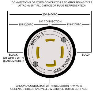
Figure 57
- Make sure that the equipment is connected to an outlet that matches the plug configuration.
- The equipment must not be connected to any different type of electric circuit.
- No adapter is available or should be used with this equipment.
- For countries other than the United States, Canada, and Mexico, OMAX does not supply a sufficiently rated industrial-grade plug.
- Contact a qualified electrician or service personnel to install a sufficiently rated industrial-grade plug in accordance with national, state, and local codes.
- A pin and sleeve plug, rated at least 30A, 230V, 2-pole+E (3-wire grounding), IP44 or better, having a first-make last-break protective bonding contact (earthing contact) in accordance with standards IEC 60309-1 and IEC60309-2 can fulfill this requirement.

Figure 58
- The cord must be plugged into a matching outlet that is correctly installed and grounded in accordance with all local codes and ordinances.
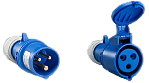
Figure 59
Explosive Atmosphere Precautions
Machining certain types of material, such as titanium, with a waterjet can cause sparks. Do not operate the equipment in an explosive environment. Do not let explosive or flammable vapors collect in the area of the equipment.
Removal of Waste Materials
Discard all machining wastes correctly in accordance with all local and federal regulations. Abrasive waterjet machining causes two types of waste: the water used for machining and the solid material that collects in the catcher tank. Although the used garnet abrasive is not dangerous, the waste deposited from the cut material can require special treatment.
In abrasive waterjet machining, high-pressure water with garnet abrasive particles hits and cuts the material. The abrasive grit and eroded particles from the cut material collect and settle at the bottom of the catcher tank until discarded. Different materials can have different requirements to discard them correctly. Always refer to all local and federal regulations. For example, when poisonous materials such as lead or radioactive metals are cut, the correct steps must be taken to discard the poisonous or radioactive water, material debris, and used abrasive garnet; local and federal regulations must be followed. Always refer to the local utility company for sewage or water treatment requirements and procedures to discard waste materials.
Sufficient Shop Ventilation
Make sure there is good airflow in the work area to dissipate gases, vapors, and fumes. The machine contains a large amount of water. The ambient temperature in the shop and of the water can have an effect on water evaporation. To decrease the effect on other equipment in the shop, make sure there is good airflow in the shop. Also, some materials, such as aluminum particles, are known to make hydrogen in water.
When aluminum is cut, the small particles of aluminum dust in the catcher tank react with the water to make flammable hydrogen gases. Usually, hydrogen bubbles to the surface and is released into the shop in safe, low concentrations.
Make sure no ignition sources (open flame or electrostatic discharge) are near the abrasive waterjet system.
Monitor the catcher tank for hydrogen gas bubbles when large quantities of aluminum are cut. The aluminum powder (made from the removed material) and spent garnet collect at the bottom of the catcher tank. The aluminum then reacts with the water and releases hydrogen gas. The hydrogen gas can collect in bubbles in the garnet. The hydrogen gas bubbles are flammable. Keep the garnet levels in the catcher tank low to prevent hydrogen gas bubbles from being collected within the garnet.
Do not smoke near the machine. Keep other sources of ignition or flammable materials near the machine. Be careful when materials that create sparks are cut, such as titanium, which can fire the gases in the catcher tank and cause an explosion. Remove the aluminum powder from the catcher tank before machining materials that spark.
Overpressure Protection
During operation, pump pressure is monitored to prevent an overpressure condition. If the pump pressure increases more than the factory-set maximum pressure limit, the safety relief valve starts and stops the pump.
Electrical Protection
The equipment controller includes short circuit, overcurrent, and thermal protection for the pump motor.
Electrical Disconnect/Emergency Machine Off (EMO)
An electrical disconnect/emergency machine off (EMO) switch is used to remove the primary AC electrical supply from the machine. To isolate the machine from its electrical supply, always unplug the primary AC supply power cord from its electrical supply outlet.
Safety Lid
The lid of the equipment has a safety interlock to prevent waterjet operation when the lid is open.
Safety Legend
The safety signal word panels and paragraph notifications can be shown throughout this and other documentation. Each gives the safety issue identification and recommended actions to prevent the risk. Be alert! Follow the recommended safety steps, procedures, and precautions to prevent injury or damage to the equipment.
Identifies a dangerous situation that could result in death or serious injury if not avoided.
Identifies a dangerous situation that could result in minor or moderate injury if not avoided.
Identifies situations that are important but not dangerous or related to physical injury; for example, messages related to property damage.
Used to give information, emphasize a point, or tips for easier operation.
Required Tools
The following table contains a list of tools with the appropriate sizes needed to setup the ProtoMAX.
Customer Provided Tools
These tools are not provided by OMAX or included with the ProtoMAX.
| Icon | Tool | Size(s) |
|---|---|---|
|
|
Safety gloves | |
|
|
Safety glasses | |

|
Utility knife | |
|
|
Scissors | |
|
|
Pry bar | |
|
|
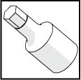
Socket wrench | |
|
|
Socket | 7/16 in. |

|
Ball-end hex wrench | 5 mm, 4 mm |
|
|
Open-end wrench | 10 mm, 13/16 in., 3/4 in. (2) |
|
|
Snips | |

|
Torque wrench | 15–102 in-lb (2–12 N·m) |

|
Crowfoot wrench | 5/8 in., 19 mm |

|
Screw driver (flat tip) | |
|
|
Flashlight | |
|
|
Hex socket | 4 mm |


OMAX Provided Tools
The following table contains a list of tools provided by OMAX needed to setup the ProtoMAX. These tools are included with the ProtoMAX.
| Icon | Tool | Size(s) |
|---|---|---|
|
|
Lifting straps | |
|
|
Dielectric compound, electrical |
|

|
Stand-off tool |


Installation Requirements
Two people are required to lift and/or move the ProtoMAX. The table is top heavy and may tilt or shift during movement. Always lift or move the table slowly to avoid injury.
See the ProtoMAX Utilities Requirements document for the equipment footprint and other technical requirements before installing the system or contact us at support@protomax.com.
What is Included
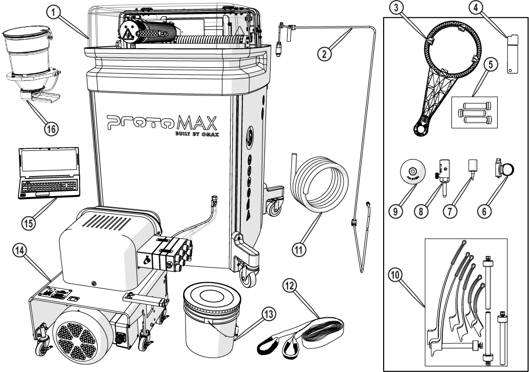
Figure 60
| [1] Table assembly | [7] Seal removal tool (not used) | [13] Garnet abrasive (55 lb) |
| [2] High-pressure plumbing assembly | [8] Nozzle assembly | [14] High-pressure pump |
| [3] Water filter wrench (not used) | [9] Nozzle splash guard | [15] Laptop with Intell-MAX® Proto installed |
| [4] Stand-off tool | [10] Material holding kit | [16] Garnet hopper assembly |
| [5] Nozzle filters (x 3) | [11] Incoming water hose | [17] Document packet (not shown) |
| [6] Hose clamp | [12] Lifting straps |
Unpack the ProtoMAX
The crated ProtoMAX weighs approximately 600 lbs (272 Kg). To avoid injury, clear the area of obstacles and debris before installation. Two or more people are required to move the ProtoMAX. Always move the ProtoMAX slowly to prevent injury or damage.
| 1. | Place the pallet near the installation location, ensuring the front of the pallet is facing away from any wall or obstruction(s). See ProtoMAX Utilities Requirements for placement and location information. |
| 2. | Remove the plastic sheeting and shipping bands from the box and discard. |

SUFFOCATION RISK! Plastic sheeting can be dangerous. Thin plastic film may cling to the nose and mouth preventing breathing. Keep the plastic bag away from babies, small children, and pets.
Plastic sheeting may be slippery. Once the plastic sheeting is removed from the ProtoMAX, remove it from the area to avoid slip, trip, and/or fall injuries.
| 3. | Carefully remove the shipping crate top and sides. |

| 4. | Remove the plastic sheeting from the ProtoMAX and discard. |
| 5. | Remove and read the document package. |
| 6. | Remove box [1] from the pallet. |

Figure 61
| 7. | Remove all items from box 1. |
| 8. | Connect power to the laptop, start the laptop, and open 401420A-EN Installation, ProtoMAX from TechDocs located in the ProtoMAX Knowledgebase for the remaining installation instructions for the ProtoMAX. |

Figure 62
| 9. | Remove the garnet abrasive [1] from the pallet, and set aside. |

Figure 63
The garnet abrasive container is very heavy. Use proper lifting techniques to avoid back and other possible injuries.
| 10. | Carefully remove the side panel kit [1] and set aside. |

Figure 64
| 11. | Sweep the floor to ensure it is free of debris and clean the area where the ProtoMAX will be placed. |
| 12. | Remove the lag bolts securing the pump to the pallet and discard. |
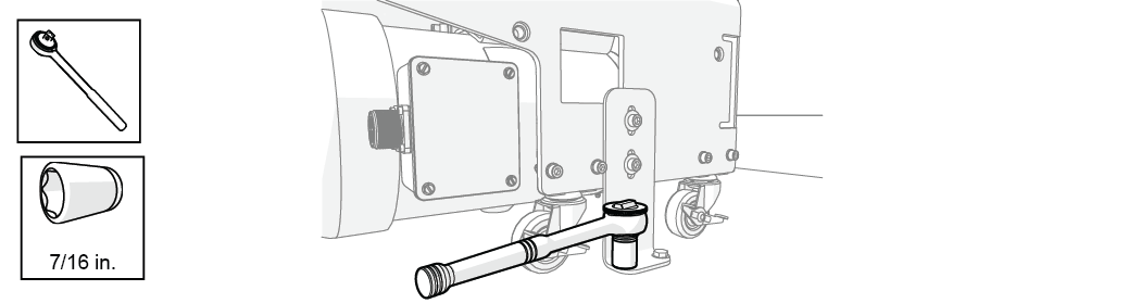
Figure 65
The pump may be moved for easier access to the side bolts.
| 13. | Remove the pump side bolts and bracket and discard. |
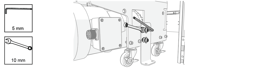
Figure 66
Two people are required to move the pump. Always move the pump slowly to avoid injury. Do not lift the pump by the safety valve or wet-end; move the pump by the frame [1] to avoid damage.

Do not tip the pump on the side. Tilting the pump may damage the caster brackets. Always move the pump by rolling it or lifting it by the frame to avoid damage.
| 14. | Unlock the pump wheels and move the pump by the frame [1] from the pallet, and set aside (Figure 67). |

Ensure the safety valve has cleared the machine frame and other components before lifting or moving off the pallet.
| 15. | Cut the straps securing the table assembly to the pallet and discard. |

Figure 68
Two or more people are required to move the table or pump. Do not lift or drag the table by the lower support legs. The table is top and rear heavy and may tilt or shift during movement. Always move the table slowly to avoid injury.

Figure 69
| 16. | Position the table for movement: |
| a. | Unlock the wheels. |
| b. | Turn the table counter-clockwise and move the table towards the left, off the shipping blocks. |
Use care when moving the table to avoid damaging the ProtoMAX power cord. The power cord may be pinched between the shipping block and the support bracket when rotating and/or moving the ProtoMAX. Pinching the power cord may damage the electrical cables inside the cord.
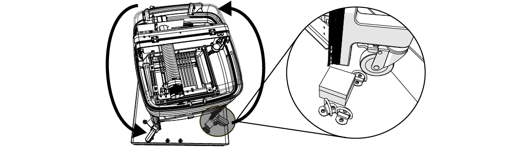
Figure 70
| c. | Remove the shipping blocks from the pallet. |

| 17. | Move the table from the pallet: |
Do not let the ProtoMAX fall to the floor. Dropping or jarring the ProtoMAX will damage the machine and internal components. When using lifting straps for movement, use the opposite (free) hand to support and guide the ProtoMAX.
| a. | Lift the table front and slowly move it forward until the ProtoMAX is midway off the pallet edge, then gently lower the legs to the ground. |

Figure 71
| b. | Lift the table rear and move the ProtoMAX off the pallet, then gently lower the table to the floor. |

Figure 72
| 18. | Roll the ProtoMAX to the installation location and lock the wheels. |
Align the wheels under the bracket before locking. Protruding wheels may cause tripping or falling hazards. To avoid injury and/or damage, lock all ProtoMAX wheels. The lock stops the wheel from rotating and rolling, which prevents the ProtoMAX from moving during operation.
| a. | Place a shipping block next to the frame leg. |
| b. | Slightly lift the frame leg with a pry bar and rotate the wheel under the bracket. |
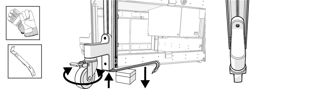
Figure 73
| c. | Lower the frame leg, lock the wheel, then remove the shipping block. |
| d. | Repeat steps 18.a.–18.c. for each frame leg. |
Set Up the ProtoMAX
Ensure the equipment is properly grounded in accordance with national, state, and local codes. Never remove any prong from the plug. Always plug into the proper electrical outlet. See the ProtoMAX Utilities Requirements document and Safety section for important grounding information. Improper connection can result in a risk of electrical shock. If the electrical outlet is NOT properly grounded, or if in doubt as to whether the tool is properly grounded, contact a qualified electrician or service personnel.
This section provides the instruction to setup up the ProtoMAX and make it ready for operation. See the ProtoMAX Utilities Requirements document for important information.
Place and Connect the Pump
DO NOT cut the black cable ties! Black cable ties secure components to the table and should remain in place. ONLY cut the orange cable ties. Orange cable ties are used to protect and secure components during shipment.
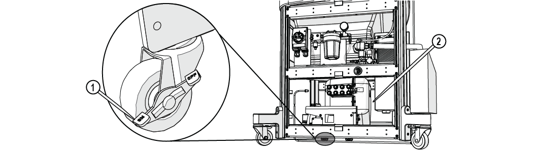
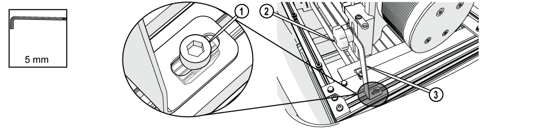
| 1. | Roll the pump under the table and lock one of the pump wheels [1]. |
Leave a 1–2 in. space [2] between the back of the pump and the control cabinet.
| 2. | Carefully remove the packing materials and connect the cooling line OUT to the push-to-connect OUT connection [1] on the pump. The cooling OUT line and connection have yellow cable ties attached. |
Connecting points are capped to prevent debris from entering into the lines. Remove the protective cap before making connections.
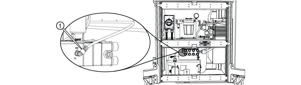
Figure 75
| 3. | Carefully remove the packing materials and connect the cooling line [1] from the IN connection on the pump to the push-to-connect fitting at the solenoid. The cooling IN lines and connections have red cable ties attached. |
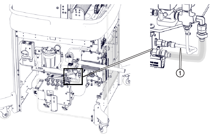
Figure 76
| 4. | Carefully remove the packing materials and connect the supply water hose from the pump wet-end [2] to the 90 degree fitting [1] and tighten. |
Do not use Teflon tape or pipe sealant on the water connections. Teflon thread or sealant particles may enter into the high-pressure plumbing system and damage the pump and/or nozzle.
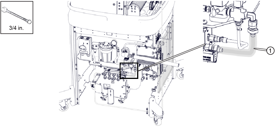
Figure 77
| 5. | Carefully remove the packing materials from the transducer cable [2] , apply a light coat of dielectric compound to the transducer cable, then connect the transducer cable to the transducer [1]. |
![]()
Figure 78
Pump Style One
![]()
Pump Style Two
| 6. | Carefully remove the packing materials, apply a light coat of dielectric compound to the pump power cord connector [1], then push the cord in and turn to connect to the pump power connector [2]. |
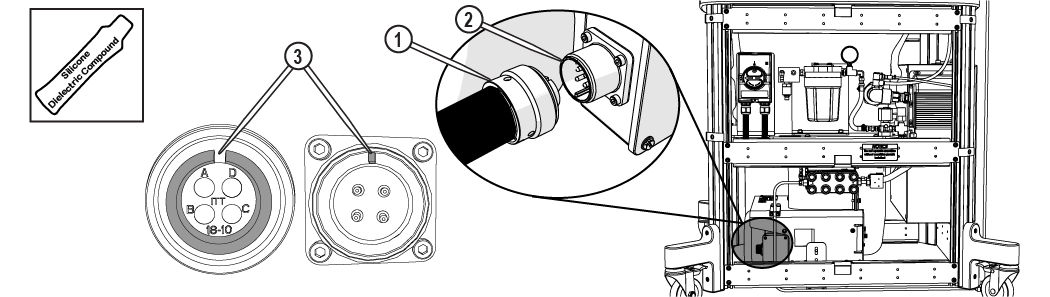
To prevent cross-threading the plug and connector, line up the notches [3] on the cable plug and power connector. Push the plug until it seats in the connector, then rotate the shell counter-clockwise until the threads engage, then turn the shell clockwise to tighten.
Connect the High-Pressure Plumbing
| 1. | Verify the u-shape high-pressure nipple, gland nut, slotted collar, and collar are assembled and aligned. |
High-pressure nipples have left-hand threads, therefore when connecting components, turn clockwise to loosen and counter-clockwise tighten. Cross threading high-pressure connections may cause leaks and/or water damage from the leak(s).
Nipples contain small caps to protect the threading and keep debris from entering the high-pressure plumbing during shipment. The caps must be removed before assembling the high-pressure plumbing fittings. Do not use pliers to remove the black caps or cut the black caps from the nipple. Pliers and knives will damage the nipple threads causing leaks and/or water damage.
When preparing the ProtoMAX high-pressure tubing, it is extremely important to follow instructions. Some high-pressure tubing and fittings are pre-assembled. Fittings may need readjustment during installation to ensure proper seals and eliminate potential leaks. Use the provided stand-off tool to ensure the fittings are properly seated and sealed.
| a. | Rotate the nipple cap clockwise to remove it from the gland nut and verify there is no debris in the high-pressure tube. |

Figure 81
| b. | Verify the collar [1] is installed in the correct position using the stand-off tool [2]; adjust the collar to the correct depth if needed. |
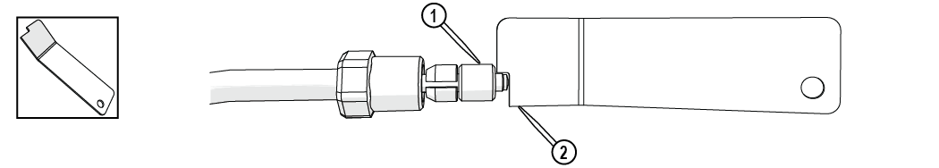
Figure 82
| 2. | Remove the bracket cap [1]. |
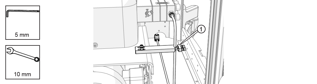
Figure 83
| 3. | Loosen the bracket. |
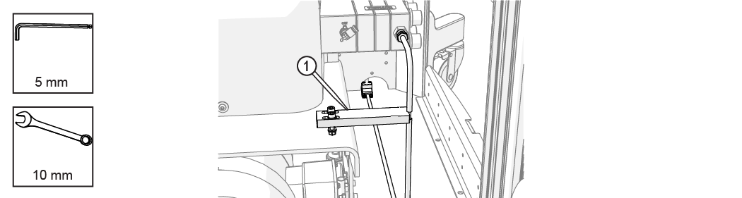
Figure 84
| 4. | Position the pump so the high-pressure plumbing is aligned vertically and horizontally, and the rear of the pump is 1–2 in. from the control cabinet. |

| 5. | Attach the assembled u-shape nipple to the pump high-pressure outlet OUT connection [1] and hand-tighten. |
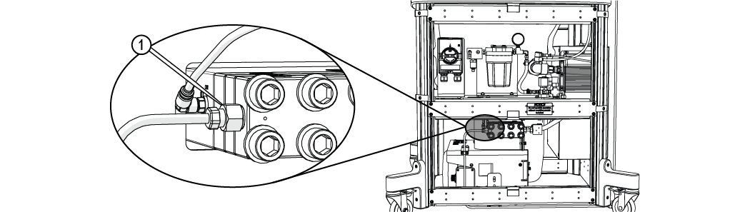
Figure 86
| 6. | Verify the gland nut is set approximately to the depth of the nozzle stand-off tool. |
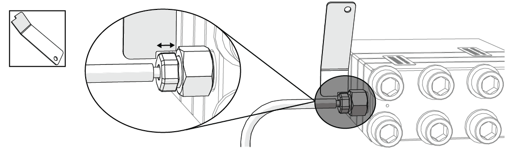
Figure 87
| 7. | Adjust the position of the bracket [1], then tighten the bracket. |
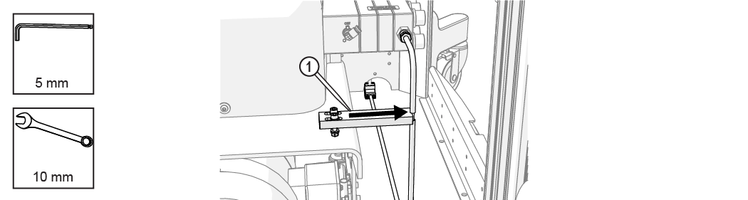
Figure 88
| 8. | Lock the pump wheels [1]. |
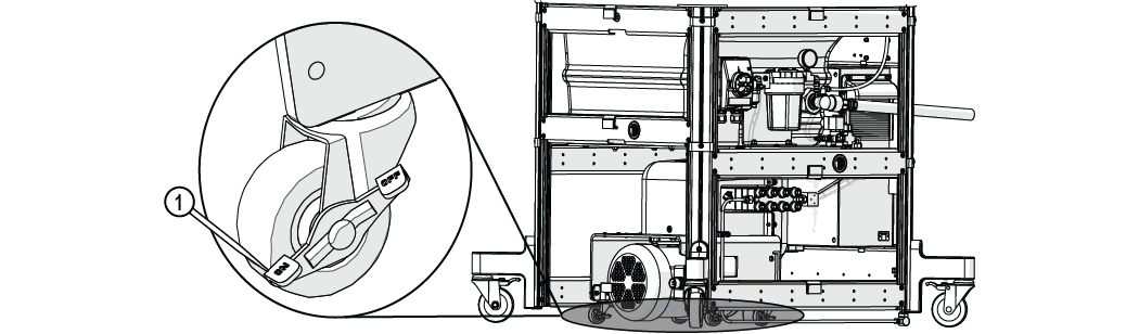
Figure 89
| 9. | Torque the pump connection. |
The jaws of the crowfoot must maintain a 90-degree angle to the horizontal axis of the torque-wrench handle throughout the torquing rotation. Other angles of orientation will alter the set torque.
Figure 90
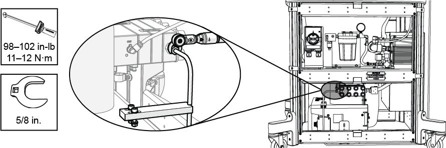
Figure 91
| 10. | Attach the bracket cap [1] and tighten. |
Ensure the flexible conduit is not trapped under the bracket.
Figure 92
| 11. | Verify the torque seals [1, 2] are not cracked or missing on all pre-assembled high-pressure connections and nozzle inlet body connection. |
Personal injury and/or damage may occur if high-pressure torque seals are cracked or missing. Contact Technical Support before operating the ProtoMAX if any high-pressure plumbing seal is cracked or missing.
Remove the Cutting Deck Shipping Materials
DO NOT cut the black cable ties! Black cable ties secure components to the table and should remain in place. ONLY cut the orange cable ties. Orange cable ties are used to protect and secure components during shipment.
| 1. | Lift the lid and lock it into the upright position. |
Use care when opening or closing the lid to avoid injury. Never let the lid free-fall. Keep hand, fingers, or body parts away from the side of the table when closing the lid.

Figure 94
| 2. | Cut the orange cable ties securing the packaged abrasive garnet hopper assembly stored beneath the lid. Lift the package from the tank and set it aside for later. |

| 3. | Loosen the thumb screws and remove the right garnet bin, then remove the desiccant packets from the tank. |
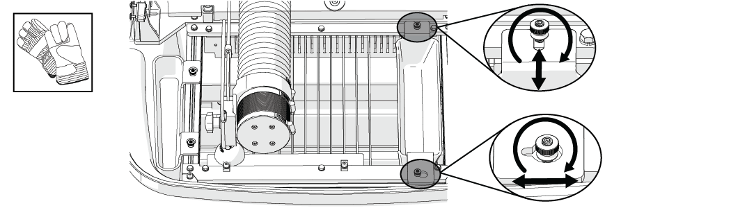
Figure 95
| 4. | Remove the drain hose and incoming water hose, and armor plate protective packaging from the tank and set aside. |
If needed, loosen the cutting deck bolts, lift the cutting deck, then re-tighten the bolts.
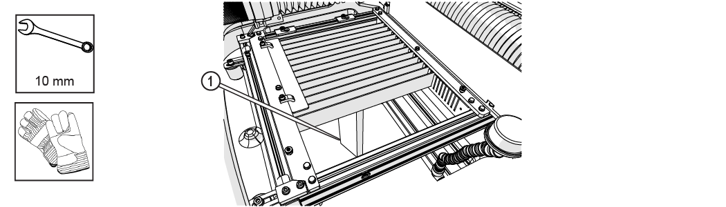
Figure 96
| 5. | Reinstall the garnet bin. |
| 6. | Remove the remaining packing materials from the slats and bellow protector. |
Do not discard the Z-axis shipping support assembly. The shipping support must be installed to prevent damage to the Z-axis bridge anytime the ProtoMAX is moved.
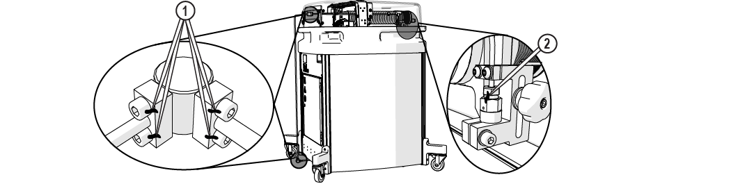
| 7. | Loosen the t-nut and bolt [1], align the t-nut with the frame slot and lift the support bracket assembly [3] from the frame (Figure 97). |
Lightly tap the bolt to loosen t-nut from the frame, if needed.
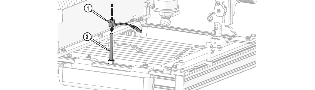
| 8. | Loosen the hand knob [2] and remove the support bracket [3]. |
Hold the inlet body when loosening the hand knob. Do not let the inlet body fall and strike the cutting deck slats. Damage to the inlet body may occur, which may cause leaks.
| 9. | Tighten the hand knob [2] (Figure 97). |
| 10. | Loosen the screws [1], remove the rear support bracket, then tighten the screws. |
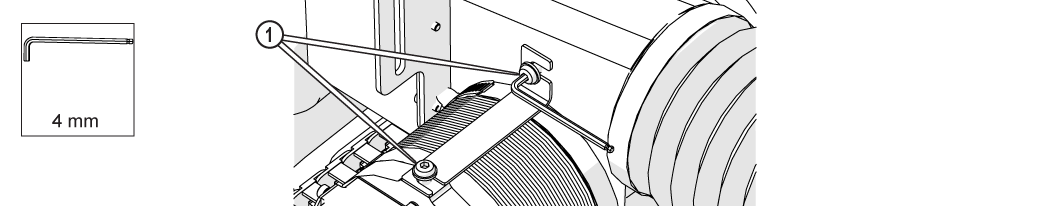
Figure 98
Connect the Drain Hose
| 1. | Remove the drain hose from its storage in the ProtoMAX tank. |
| 2. | Insert the drain hose through the hole [1] at the rear of the enclosure. |
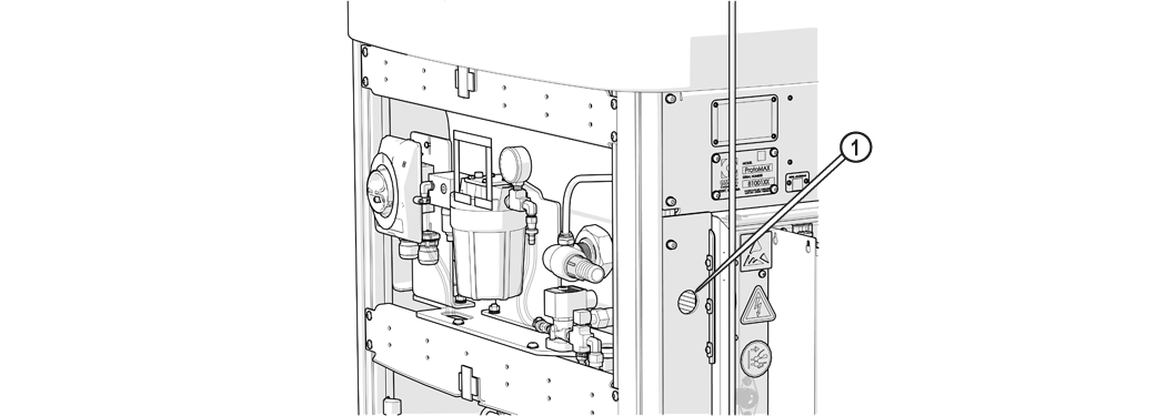
Figure 99
| 3. | Slide the hose completely onto the barbed hose fitting [1]. |
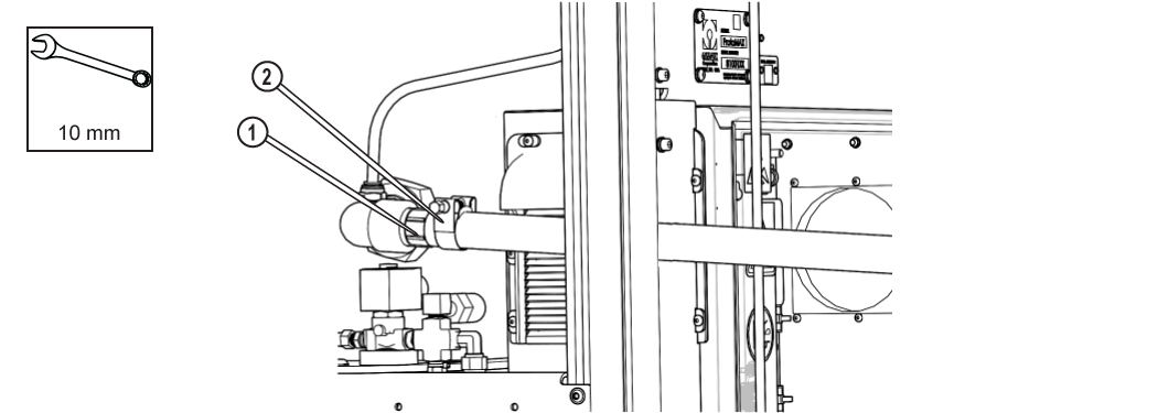
Figure 100
| 4. | Position the hose clamp around at least two barbs on the fitting, then tighten the hose clamp until the clampends are from 0 to 1/16 in. (0 to 1.5875 mm) apart. |

Figure 101
| 5. | Connect the incoming water line to the manifold IN connection [1] and secure with the hose clamp. |
Install the Garnet Abrasive Hopper
The garnet abrasive assembly was originally stored under the tank and removed and set aside in a previous step. See Remove the Cutting Deck Shipping Materials.
| 1. | Locate the garnet abrasive hopper assembly and carefully remove the packing materials. |
| 2. | Adjust the cutting deck light to access the hopper mounting location [1]. |

Figure 103
| 3. | Cut the orange cable tie securing the grounding cable.  |
| 4. | Attach the hopper assembly [1] to the exterior of the roll bar with the supplied hardware [2]. |
Ensure the ground connection located inside the roll bar is attached to the inward hopper mounting bolt [2]. Order on bolt is washer, grounding cable, then lock washer.
DO NOT cut the black cable ties! Black cable ties secure components to the table and should remain in place. ONLY cut the orange cable ties. Orange cable ties are used to protect and secure components during shipment.
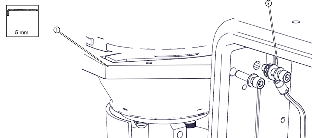
Figure 104
| 5. | Insert the hopper assembly in its mounting bracket [1]. |
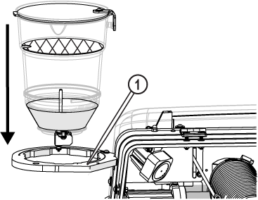
Figure 105
| 6. | Insert the abrasive feed tube through the roll bar [2], then insert the feed tube into the abrasive feed block [1]. |
Verify the abrasive feed tube is not kinked or twisted.
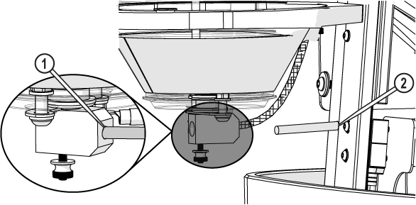
Figure 106
| 7. | Attach the hopper splash guard [1] to the hopper bottom, ensuring the washer is on the bottom of the hopper splash guard, then tighten the thumb screw [2]. |
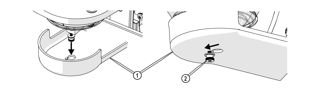
Figure 107
| 8. | Remove the shipping materials from the abrasive screen and place the garnet abrasive screen in the hopper. |
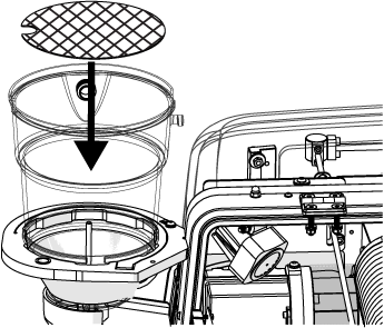
Figure 108
| 9. | Fill the hopper with garnet abrasive. |
Only use garnet abrasive purchased from OMAX.
| a. | Pour the garnet abrasive through the garnet abrasive screen into the hopper. |
Gently tap the hopper side to evenly settle the garnet abrasive in the hopper.
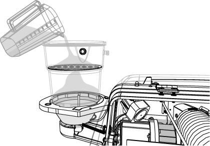
| b. | Place the hopper lid on the top of the hopper and secure the latching device. |
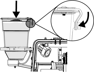
Figure 110
| 10. | Close the machine lid. |
| a. | Lift the lid and push support arm towards the back. |
Use care when opening or closing the lid to avoid injury. Never let the lid free-fall. Keep hand, fingers, or body parts away from the side of the table when closing the lid.

Figure 111
| b. | Lower the lid to the catcher tank. |
Power ON the ProtoMAX
Ensure the equipment is properly grounded in accordance with national, state, and local codes. Never remove any prong from the plug. Always plug into the proper electrical outlet. See the ProtoMAX Utilities Requirements document and Safety section for important grounding information. Improper connection can result in a risk of electrical shock. If the electrical outlet is NOT properly grounded, or if in doubt as to whether the tool is properly grounded, contact a qualified electrician or service personnel.
| 1. | Remove the cable tie securing the power cable to the frame. |
| 2. | Route the cable and connector under the bottom-rear support bracket. |
| 3. | Remove the packing materials from the cable connector. |
| 4. | Plug the power cord into the main power outlet. |
For countries other than United States, Canada and Mexico, OMAX does not supply a suitably rated industrial grade plug.
Contact a qualified electrician or service personnel for installation of a suitably rated industrial grade plug in accordance with national, state, and local codes. A pin and sleeve plug, rated at least 30A, 230V, 2-pole+E (3-wire grounding), IP44 or better, having a first-make last-break protective bonding contact (earthing contact) in accordance to standards IEC 60309-1 and IEC60309-2 may fulfill this requirement. You must plug the cord into a matching outlet that is properly installed and grounded in accordance with all local codes and ordinances.

Figure 112
| 5. | Connect the laptop power cord into the laptop and to a 110 volt outlet, if needed. |
For other voltages, the laptop power supply is rated 100-240V, 50/60HZ.
| 6. | Power ON the laptop. |
Allow the laptop to completely boot before connecting the USB cable.
| 7. | Remove the USB cable from the top of the Control Box and remove the packaging. |
| 8. | Route the USB cable [1] through the bottom back of the machine. |
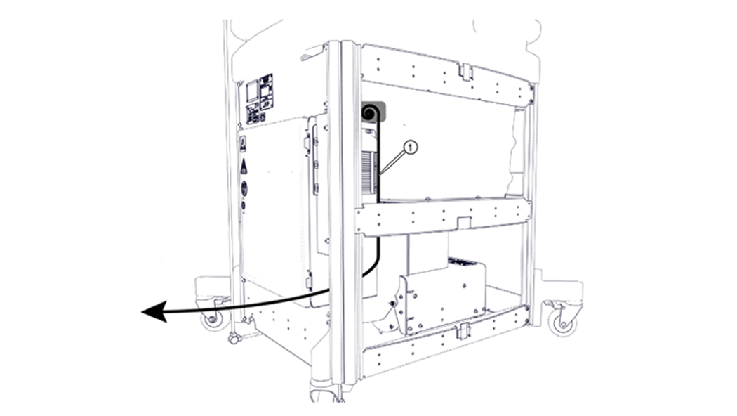
Figure 114
| 9. | Connect the USB cable to the laptop. |

Figure 115
| 10. | Turn the power switch ON [1] and verify the cutting deck light is on. |
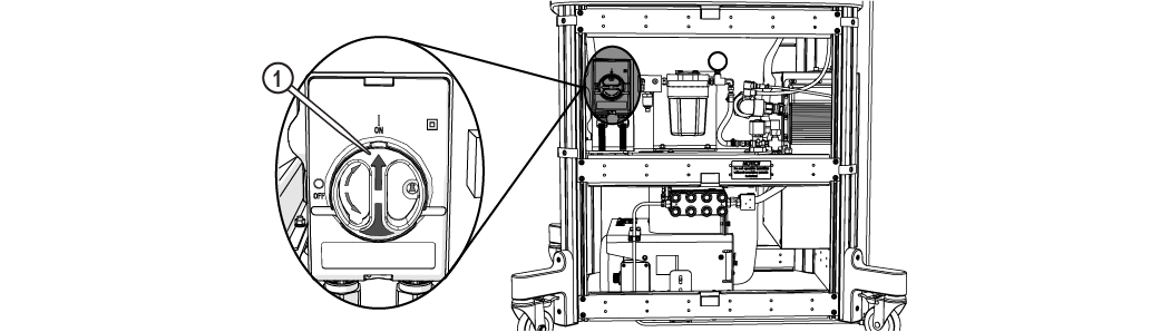
Figure 116
| 11. | Open MAKE and observe the color of the numbers in Nozzle Position pane [1]. |
- Bright green - the ProtoMAX and laptop are communicating
- Dull green - the ProtoMAX and laptop are not communicating
- Yellow - the laptop is not connected to the ProtoMAX

Figure 117
| 12. | Remove any tools and/or obstacles from the cutting deck. |
| 13. | Home the machine. |
| a. | Read the Warning and click . |
| b. | Click the icon. |

Figure 118
| c. | Read the Warning and click . |
Flush the High-Pressure Plumbing
Flushing the system ensures there is no debris in the high-pressure plumbing that can clog the nozzle during operation.
Plugs or caps on the ProtoMAX system indicates required connections. To avoid injury and/or damage, verify all water and high-pressure connections are made before continuing. Contact OMAX Technical Support if needed.
| 1. | Open and secure the lid. |
Use care when opening or closing the lid to avoid injury. Never let the lid free-fall. Keep hand, fingers, or body parts away from the side of the table when closing the lid.
Figure 119
| 2. | Unscrew the protective cap from the inlet body and verify the nozzle filter [1] is not installed; remove the nozzle filter if installed and discard. |

Figure 120
| 3. | Loosen the Z-axis [1] and lower it to the lowest position. |
Hold the inlet body when loosening the hand knob. Do not let the inlet body fall and strike the cutting deck slats. Damage to the inlet body may occur, which may cause leaks.

Verify the abrasive feed tube is not connected to the nozzle.

Figure 122
| 4. | Close the lid. |
Use care when opening or closing the lid to avoid injury. Never let the lid free-fall. Keep hand, fingers, or body parts away from the side of the table when closing the lid.
| 5. | Connect the other end of the incoming water line to the water source (connection to the water source is customer supplied). |
Do not pinch or trap any wires in the opening. Pinching or trapping may damage the wrapped cable, causing communication errors or inaccurate water temperature readings.
| 6. | Open the main water source. |
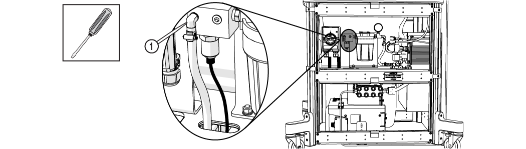
| 7. | Push the button [1] on the water filter to release the air. |
Place a rag over the top of the water filter to prevent water from spraying.
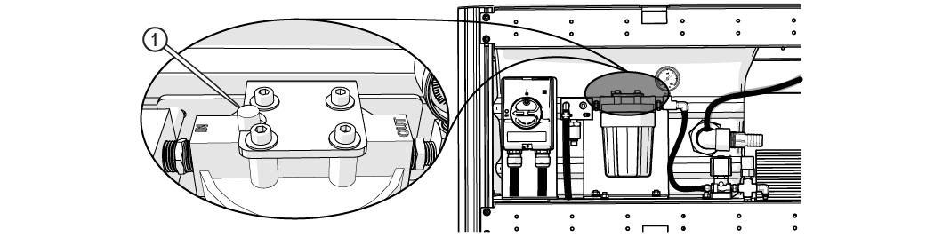
Figure 123
| 8. | Check for leaks at the incoming water [1] , filter out [2], solenoid [3], solenoid to pump [4], cooling line to pump [5], cooling line IN [6], and pump incoming water [7] connections. |
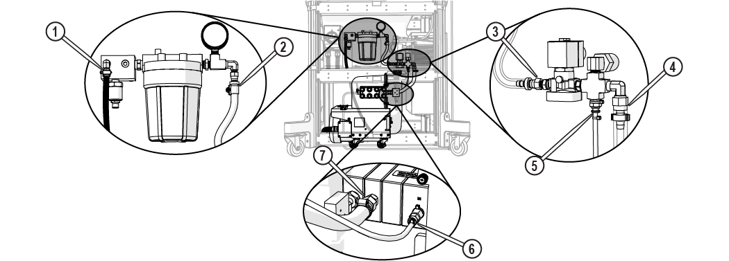
Figure 124
| 9. | In MAKE, use the X, Y Jog buttons [1] or the keyboard arrow keys to position the nozzle between two slats in the center of the cutting deck. |

Figure 125
| 10. | Click Test [1]. |

Figure 126
| 11. | In the Test Operations dialog box, select Flush plumbing, click . |

Figure 127
Verify the abrasive feed tube is not connected to the nozzle.
Figure 128
| 12. | Click . |
The flush test will run for 30 minutes. The pump will cycle on and off during the test operation, but water will still flow. The test automatically stops after 30 minutes.
Keep a minimum of 16 in. (40 cm) away from pressurized equipment during operation. Do not try to tighten ultra-high-pressure (UHP) fittings while the system is under pressure. Do not touch or rub suspected high-pressure plumbing leaks. Rubbing or touching suspected high-pressure leaks may result in injury. If a leak is found, shutdown the system, then fix the leak before continuing. Never attempt to fix a leak while the ProtoMAX is running.
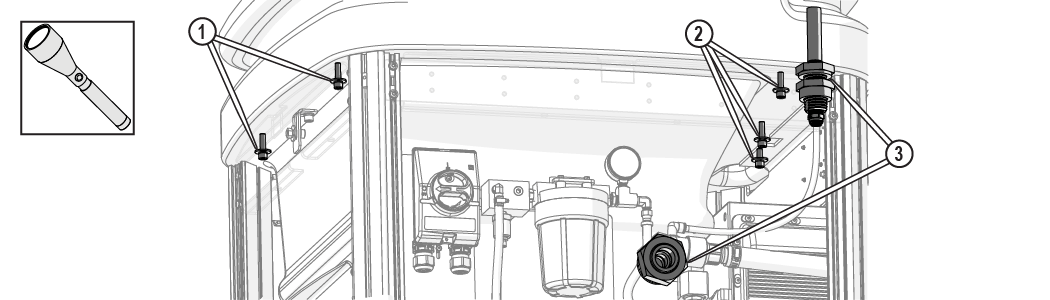
| 13. | Check the high-pressure plumbing for leaks at the nozzle [1], high-pressure fittings [2], pump connection [3] and safety release valve [4] during the test operation. |
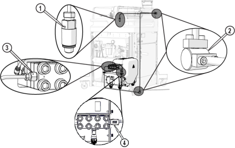
- If a leak is found, shut down the system and torque the connection using the information in the following table.
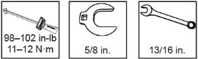
The jaws of the crowfoot must maintain a 90-degree angle to the horizontal axis of the torque-wrench handle throughout the torquing rotation. Other angles of orientation will alter the set torque.
Figure 130
| Tools and Torque Specification | Location |
|---|---|
 | Pump [1] |
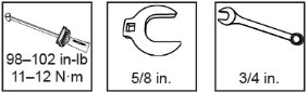 | Nozzle [2] |
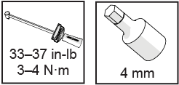 | High-pressure fitting [3] |
| 14. | Click when the flush is complete. |
| 15. | Fill the tank with water up to the top of the slats and check for leaks at the tank front [1], tank rear [2], and tank drains [3]. |
Install the Nozzle
Do not install the nozzle before performing the initial system flush.
| 1. | Open and secure the lid. |
Use care when opening or closing the lid to avoid injury. Never let the lid free-fall. Keep hand, fingers, or body parts away from the side of the table when closing the lid.
Figure 133
| 2. | Place a piece of cardboard or other material on top of the slats to keep small parts from falling into the tank. |
| 3. | Raise the Z-axis plate. |
Hold the inlet body when loosening the hand knob. Do not let the inlet body fall and strike the cutting deck slats. Damage to the inlet body may occur, which may cause leaks.
| 4. | Install the nozzle filter [1] into the inlet body. |
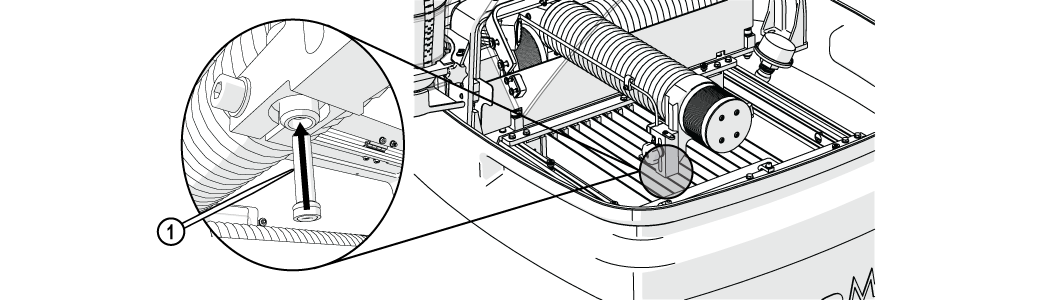
Figure 134
| 5. | Carefully remove the protective cap from the nozzle assembly. |
Always orient the orifice assembly so the brass [1] is visible from the top of the nozzle body. Inserting the orifice assembly in nozzle body in the incorrect orientation [2] may cause damage to the orifice assembly.

Figure 135
| 6. | Insert the orifice assembly [1] into the nozzle body and adjust the orifice to ensure the it is seated correctly in the chamber bore [2]. |
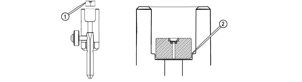
Figure 136
Do not use a brush or cotton swab or foam-tipped applicator to apply lubricants because they may leave fibers and clog the nozzle.
| 7. | Apply a light coat of Blue Goop to the second and third threads [1] of the inlet body, then spread the lubricant evenly around the inlet body threads. |
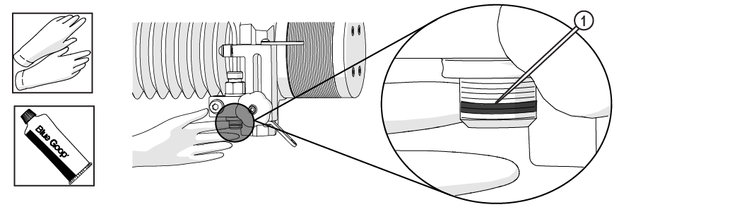
Figure 137
| 8. | Wipe the excess Blue Goop from the end of the inlet body [1]. |
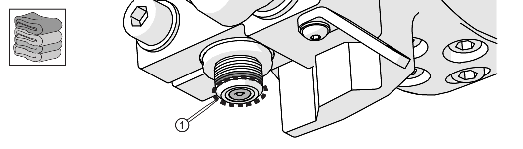
Figure 138
| 9. | Apply a light coat of blue goop to the first and second nozzle body threads [1], then spread the lubricant evenly around the nozzle body threads. |

Figure 139
| 10. | Wipe the excess Blue Goop from the end of the nozzle body [1]. |

Figure 140
| 11. | Attach the nozzle [3] to the inlet body [1]. |
Ensure the garnet abrasive inlet [2] points towards the front of the table. Move the Z-axis to the back of the cutting deck (+Y direction) prior to tightening.
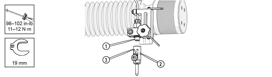
Figure 141
Remove the thumb screw [1] and mixing tube [2] from the nozzle body if necessary to fit the torque wrench prior to tightening. Hold onto the mixing tube [2] so that it does not drop out of the nozzle body when the thumb screw [1] is removed.
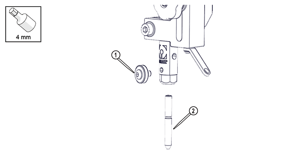
Figure 142
| 12. | Verify the mixing tube is properly seated into the nozzle body and the thumb screw is tightened. |
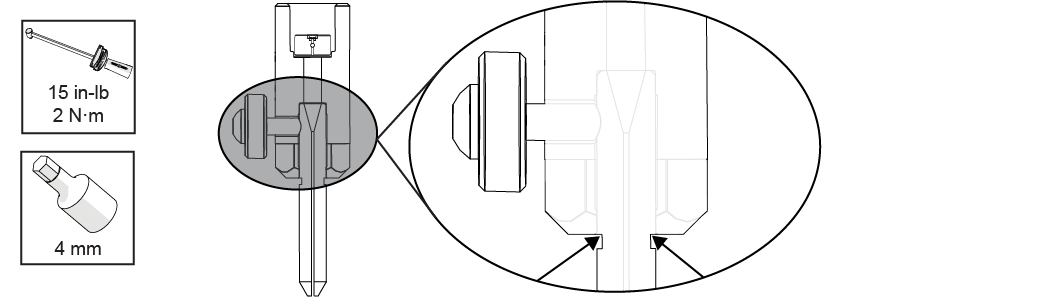
Figure 143
| 13. | Place the nozzle splash guard onto the mixing tube, then fold the splash guard cup. |

Figure 144
| 14. | Close the lid. |
Use care when opening or closing the lid to avoid injury. Never let the lid free-fall. Keep hand, fingers, or body parts away from the side of the table when closing the lid.
Test the ProtoMAX

Before operating the ProtoMAX verify the PC, electrical, and water connections are secure.
Ensure the equipment is properly grounded in accordance with national, state, and local codes. Never remove any prong from the plug. Always plug into the proper electrical outlet. See the ProtoMAX Utilities Requirements document and Safety section for important grounding information. Improper connection can result in a risk of electrical shock. If the electrical outlet is NOT properly grounded, or if in doubt as to whether the tool is properly grounded, contact a qualified electrician or service personnel.
Verify the abrasive feed tube is not connected to the nozzle.

Figure 145
| 1. | Run the Reset Pump test operation. |
The reset pump test runs a 30 second sequence to reset the pump. This test should be done before operating the ProtoMAX for the first time, after changing the nozzle orifice, repairing or replacing the pump, repairing any high pressure plumbing leaks, or when required by a fault or alert message.
| a. | Open MAKE. |
| b. | Move the nozzle between two slats. |
| c. | Click . |
| d. | In Test Operations, select Reset Pump, and click . |
| e. | Click and check the high-pressure plumbing for leaks (the dialog box closes when the test is complete). |
| 2. | Verify the lid safety switch operation. |
The cutting stage lid has a built-in safety interlock to halt all cutting operations (pauses MAKE, stops stage motion, and turns off the pump) when the lid is opened.
| a. | In Test Operations, select Test Cutting Head (Pump, Jet, and Abrasive), and click . |
| b. | Click . |
| c. | Open the lid to verify the test stops (the pump turns off, MAKE pauses, and stage motion stops). |
| d. | Close the lid. |
| e. | Verify the X-axis and Y-axis moves. |
| 3. | Test the nozzle without abrasive. |
| a. | Open and secure the lid. |
Use care when opening or closing the lid to avoid injury. Never let the lid free-fall. Keep hand, fingers, or body parts away from the side of the table when closing the lid.
Figure 146
Verify the abrasive feed tube is not connected to the nozzle.
Figure 147
| b. | Position the nozzle in the center of the tank, between two slats. |

Figure 148
| c. | Close the lid. |
Use care when opening or closing the lid to avoid injury. Never let the lid free-fall. Keep hand, fingers, or body parts away from the side of the table when closing the lid.
| d. | Click [1]. |
Figure 149
| e. | In Test Operations, select Test Cutting Head (Pump, Jet, and Abrasive), and click . |

Figure 150
| f. | Click . |

Figure 151
| g. | Click when the test is complete. |
| 4. | Test the nozzle with abrasive. |
| a. | Insert the abrasive feed tube into the garnet abrasive inlet [1]. |

Figure 152
| b. | Click Test [1]. |
Figure 153
| c. | In Test Operations, select Test Cutting Head (Pump, Jet, and Abrasive), and click . |
Figure 154
| d. | Click . |
Figure 155
| e. | Observe the garnet abrasive tube [1] to verify abrasive is flowing. |

Figure 156
| f. | Click when the test is complete. |
The nozzle test automatically stops and closes the Test in progress ... window after 60 seconds.
Install the Material Holding Kit
The material holding kit is an optional ProtoMAX accessory that helps stabilize materials on the cutting stage.
| 1. | Loosen the t-nut all the way, but do not remove it from the part holding post. |
| 2. | Align the part holding post assembly with the channel. |

Figure 157
| 3. | Set the part holding assembly in the channel and begin tightening, the t-nut [1] rotates perpendicular to the channel, then tighten to secure. |
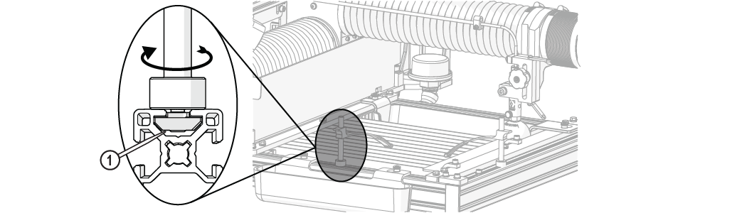
Figure 158
| 4. | Place the material clamp [1] on the part holding post [2] and press down to secure. |
| 5. | Lift up on the back of the arm [1] or rotate the arm sideways and lift to remove (Figure 159). |
Install the Bottom Support Bracket and Side Panels
| 1. | The bottom frame support bracket is in a package located behind the middle frame support bracket. To remove it, grasp it on the left side and carefully lift it diagonally from the frame. |
Always lift the bracket diagonally from the left end. The bracket cannot be removed by lifting straight up.
| 2. | Remove all packing materials from the bottom frame support bracket. |
| 3. | Install the bottom frame support bracket [1] using the provided hardware. |
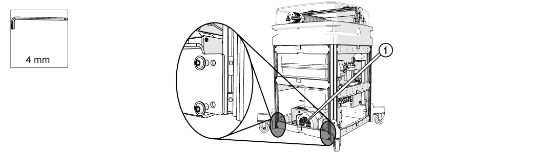
Figure 160
| 4. | Install the side panels: |
| a. | Slide one end of the panel into the support leg slot. |
Support the bottom of the panel while inserting the edges into the frame support.
| b. | Press the other side of the panel down into the opposite support leg slot. |

Figure 161
| c. | Press on the center of the panel to secure it to the table frame. |
| d. | Repeat steps 1–3 for each panel. |
The ProtoMAX installation is complete and ready for operation. Refer to the document, 401434 Operation, ProtoMAX.
Cut the Fixturing Square
See the fixturing-square instructions and video for additional information on cutting the fixturing square.
A fixturing square [1] establishes an X and Y reference to a known point in the cutting deck (Figure 162). The square provides a stable base for securing parts for cutting, and assists in maximizing material use when cutting. It can be used to precisely locate features on existing parts, or as a convenient surface to secure material against when cutting.
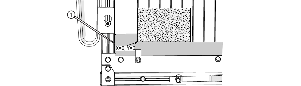
A square fixture is made by clamping material along the X-front frame in the machine cutting deck, and then using the machine to cut an "L" shape into it. Since the machine cuts the "L," we know it to be true and square to the machine's X- and Y-axes.
Technical Support
Refer to omax.com for technical support information.
Warranty
Contact Customer Support or go to the ProtoMAX website.