
________________________________________
Fixturing Square
A fixturing square establishes an X and Y reference to a known point in the cutting deck. The square provides a stable base for securing parts for cutting, and assists in maximizing material use when cutting. It can be used to precisely locate features on existing parts, or as a convenient surface to secure material against when cutting.
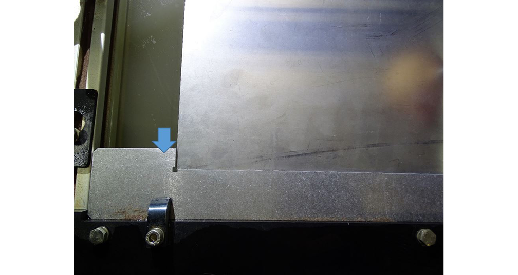
A square fixture is made by clamping material along the X-front frame in the machine cutting deck, and then using the machine to cut an "L" shape into it. Since the machine cut the "L," we know it to be true and square to the machine's X- and Y-axes.
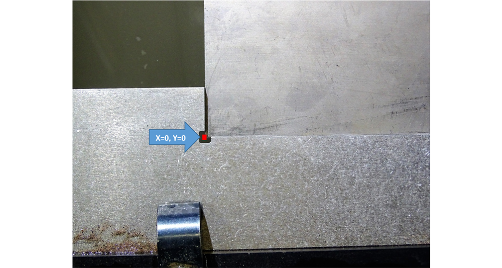
Once the cut is complete, the machine returns to the corner of the "L," which becomes your "square." The corner of the square is designed to be at the X=0, Y=0 coordinate position on your machine. Your machine automatically moves to this position when it performs the Automatic Homing routine at machine startup, or when you Re-Home the machine using the MAKE software.
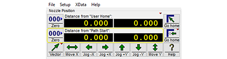
You could use this corner point as a nozzle home position for cutting your parts, but if your part geometry runs adjacent to the square fixture, you may cut into the square fixture. Instead, it is a best practice to set your Path Start point slightly off this X=0 and Y=0 home point prior to beginning the machining process. You can move the nozzle to another point in the cutting area and use that position as a starting point for your cutting path.
When you open an OMX tool path file in MAKE, the white cross indicates the starting point for the tool path.
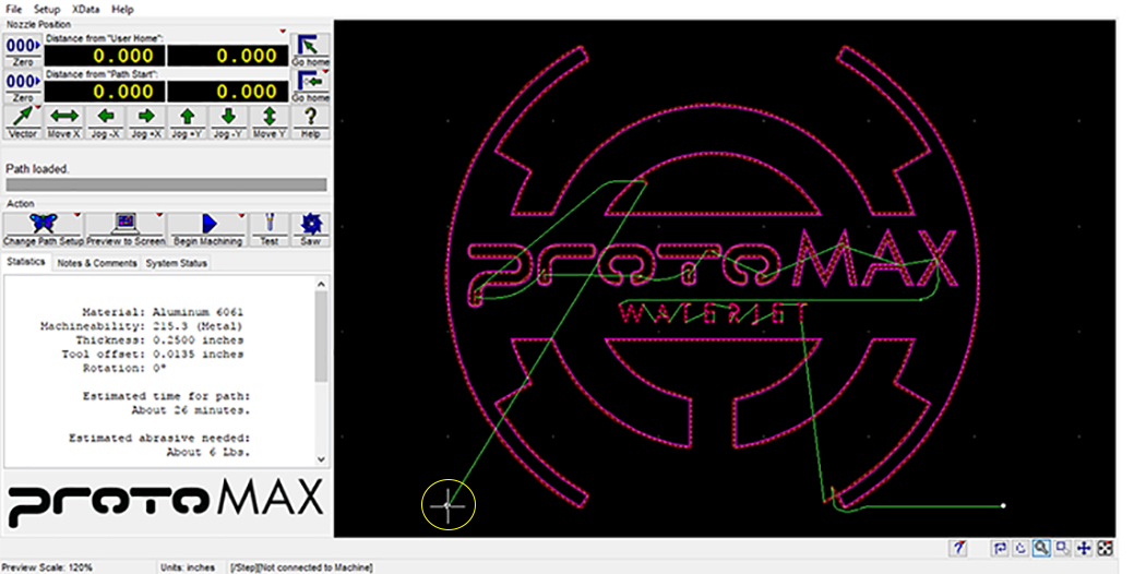
Wherever you choose to position the nozzle on your material becomes your Path Start Home position, whether in the corner of the square, or elsewhere on your material.
Easily cut a square for fixturing parts using the OMX file provided with your software.