ProtoMAX®
Polymer Cutting Deck Guide
 Install the Polymer Cutting Deck

|
OMAX Corporation
|
|
Information:
|
info@protomax.com
|
This document contains subject matter to which OMAX® Corporation has proprietary rights. Recipients of this document shall not duplicate, use, or disclose information contained herein, in whole or in part, for any use other than the purpose for which this manual was provided.
OMAX Corporation believes the information described in this manual is accurate and reliable. From time to time, design improvements will be made to the OMAX equipment. Photographs, text, and sketches within the body of this manual may not exactly represent your equipment. In general, this manual contains the most up-to-date information available. However, OMAX Corporation cannot accept any responsibility, financial or otherwise, for any consequences arising out of the use of this material. The information contained herein is subject to change, and revisions may be issued to advise of such changes or additions. OMAX strives to continually improve user documentation. If you have any questions or concerns about the content of this user’s guide, please e-mail us at tech_writing@omax.com, or contact us by mail at:
OMAX Corporation
Technical Publications
21409 72nd Avenue South
Kent, WA, USA 98032
OMAX Corporation is continually improving their equipment to bring you the best in abrasive waterjet machining technology. For that reason, your abrasive waterjet may differ slightly from what is described in this document. If you have any questions, please feel free to contact us at 1-800-298-4036 or e-mail us at info@protomax.com. You can also receive technical support on-line at: Web: http://www.protomax.com.
Original Instructions in English
April 2018
© 2018 OMAX Corporation
Machine Safety Labels
These safety labels can appear on the equipment. If ignored, physical injury, death, or equipment damage may occur. Read the complete safety information in the operation, installation, or maintenance guide before the equipment is installed, operated, or maintained.

WARNING Electrical Shock
Dangerous voltages. Do not access areas with this label before the applicable safety precautions are done; lockout/tagout the power and make sure there is no voltage on the circuits before installation, maintenance, or other work is done.

WARNING Airborne Debris
Eye protection and hearing protection are required during operation. Do not remove the abrasive feed tube from the nozzle or hopper when pressurized. The pressure can blow abrasive into the air, and the abrasive particles can get into the eyes and contaminate tools and machines.

WARNING Keep Fingers and Hands Away From Parts that Move
Keep hands and fingers away from the machine when it moves and during operation. Fingers and hands can be crushed and cut by machine parts when they move. Do not try to gain access to the machine or parts during operation.

WARNING Pinch Risk
Keep hands away from the edge of the catcher tank when the lid is closed.

WARNING Keep Hands Away From Jet
Do not put hands or fingers near the nozzle during operation. Immediately get medical aid for abrasive waterjet injuries. Injuries caused by high-pressure abrasive waterjet systems are dangerous. Do not wait to get medical aid!

WARNING Watch Hands and Fingers
Always keep the motor guards in position during operation. Keep hands away from belts and pulleys during maintenance and service.

Electrostatic Discharge
Attention! Be careful when electrostatic-sensitive devices are touched. Use electrostatic discharge protection procedures.

No Open Flame
Do not smoke near the equipment. Do not operate the equipment in an explosive atmosphere. Make sure ignition sources (such as flames or electrostatic discharge) are not near the equipment. Do not store flammable materials near the equipment. Do not use equipment in or around flammable gases or liquids. Do not let explosive or flammable vapors collect in the area around the equipment. Make sure there is good airflow in the work area to dissipate gases, vapors, and fumes. Be especially careful when machining materials that create sparks, such as titanium, which can cause gases in the catcher tank to explode.

Do Not Operate With Guard Removed
Do not operate when the guards or panels are removed.

Do Not Spray
Do not spray water on or near the machine's electrical enclosure.

Do Not Step
Do not step, stand, or walk on the slats. The slats can become weak after operations and can fall under more weight.

Read Manual First/Do Not Adjust
Do not adjust. Read the manual. Special instructions could be required before adjustments are made. Adjustments to the equipment can have unwanted effects and cause injury or damage.

MANDATORY ACTION Disconnect Power
Always disconnect the primary power cord from the electrical source to isolate the machine from its electrical supply.

Read Manual
Read the equipment operation guide for important safety information and operation instructions. Do not operate this machine until all safety precautions and operation instructions are read and understood.

Wear Hearing Protection
Always wear hearing protection when near the equipment during operation. When operated above water, noise levels can exceed 70 dBA.

Wear Eye Protection
Always wear approved safety glasses when the abrasive waterjet system is operated. Other types of glasses do not give sufficient eye protection! The garnet abrasive is not a chemical irritant, but garnet can cause an eye injury like sand if it is not quickly flushed. Also, the catcher tank water can contain particles from the material or other chemical irritants. Have an eye-wash station near the work area if the abrasive spray gets into the eyes.
Read the product labels and refer to product Safety Data Sheets (SDS) to identify the properties and risks of chemical products and materials referenced in this document. Use good industrial hygiene, safety practices, and personal protective equipment identified in the SDS.

Wear Gloves
The catcher tank water can have dangerous bacteria in it. A small break in the skin can introduce the dangerous bacteria into a wound. Always wear protective gloves if there are cuts or wounds on the hands or fingers. When material is put on or removed from the slat bed, wear gloves that give protection against sharp metal edges.
Read the product labels and refer to product Safety Data Sheets (SDS) to identify the properties and risks of chemical products and materials referenced in this document. Use good industrial hygiene and safety practices. Use personal protective equipment as specified in the SDS.
Safety Legend
The safety signal word panels and paragraph notifications can be shown throughout this and other documentation. Each gives the safety issue identification and recommended actions to prevent the risk. Be alert! Follow the recommended safety steps, procedures, and precautions to prevent injury or damage to the equipment.
Identifies a dangerous situation that could result in death or serious injury if not avoided.
Identifies a dangerous situation that could result in minor or moderate injury if not avoided.
Identifies situations that are important but not dangerous or related to physical injury; for example, messages related to property damage.
Used to give information, emphasize a point, or tips for easier operation.
Required Tools
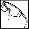
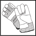
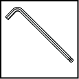
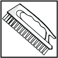
The following table contains a list of tools with the appropriate sizes that are needed to maintain the ProtoMAX. Tools listed with part numbers are included with the ProtoMAX.
| Icon | Tool | Size(s) |
|---|---|---|
|
|
Safety Glasses | |
|
|
Gloves, latex | |

|
Open-end wrench | 10 mm |
|
|
Gloves, safety | |
|
|
Allen wrench | 5 mm |
|
|
Brush | |
|
|
Spray bottle |
Overview
Small parts can easily fall into the catcher tank after cutting. The polymer cutting bed provides a stable cutting platform that helps support the part while cutting, reducing the need for tabs. The density of the polymer cutting bed minimizes splashing and reduces noise during the cutting process. The reduced splashing helps to minimize movement when cutting parts from thin materials. Reduced splashing also minimizes frosting on the underside of parts. This guide provides the instructions to remove the slat bed assembly, install the polymer cutting bed assembly and replace the polymer cutting bed.
Components
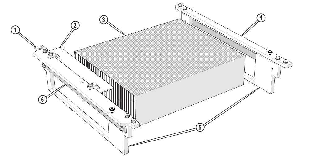
Figure 1
| [1] Mounting plate, front | [3] Polymer board cutting bed | [5] Slat comb |
| [2] Cutting plate square | [4] Mounting plate, rear | [6] Slat comb support (x 2) |
Preparation

| 1. | Drain water to below the garnet bins. |
| 2. | Remove material holding kit, if installed. |
| 3. | Move the X and Y-axes so the Z-axis is in the upper left corner of the cutting bed. |
| 4. | Raise the Z-axis to the maximum upper position. |
| 5. | Shut down the machine. |
| 6. | Remove the abrasive feed tube from the nozzle. |
Remove the Slat Bed Assembly

Bacteria in the tank water can build up. A minor break in the skin can introduce harmful bacteria into a wound. Always wear protective gloves if you have cuts or open wounds on your hands. Wear gloves that provide protection against sharp metal edges.
| 1. | Open the lid and lock it in the upright position. |
Use care when opening or closing the lid to avoid injury. Never let the lid free-fall. Keep hand, fingers, and body parts away from the side of the table when closing the lid.
| 2. | Remove the garnet bins. |

Figure 2
| 3. | Loosen the cutting bed bolts [1] and align the t-nuts [2] with the frame slot [3]. |

Figure 3
Use care when removing the cutting bed to avoid damage to the Y- and Z-axes and the nozzle assembly.
| 4. | Carefully lift the cutting bed out of the catcher tank. |

Figure 4
| 5. | Clean the frame t-slot [1] by spray with a strong stream of water. |

Figure 5
Install the Polymer Cutting Bed Assembly

Use care when installing the cutting bed to avoid damage to the Y- and Z-axes and the nozzle assembly.
| 1. | Rotate the t-nuts to align with the frame slot. |
| 2. | Place the polymer cutting bed assembly on the frame with t-nuts in the frame slot. |

Figure 6
| 3. | Slide the polymer cutting bed forward so it is flush against the front frame [1] and aligned between the bracket mounting plates [2]. |

Figure 7
| 4. | Loosen the t-nuts completely, then tighten to lock in place. |

Figure 8
| 5. | Reinstall the garnet bins. |

Figure 9
| 6. | Re-install the material holding clamps, see Install the Material Holding Kit. |
| 7. | Fill the catcher tank with water to just below the top of the polymer cutting bed; adjust the tank drain height as needed. |
| 8. | Close the lid. |
Use care when opening or closing the lid to avoid injury. Never let the lid free-fall. Keep hand, fingers, and body parts away from the side of the table when closing the lid.
| 9. | Cut the fixturing square; see the fixturing-square instructions and video. |
Replace the Polymer Cutting bed
In time, the polymer cutting bed can become scored with deep garnet abrasive waterjet cuts and will be unable to provide the stability and support required for precision cutting.
The working life of a polymer cutting bed can be greatly improved by cutting at different table locations.
Bacteria in the tank water can build up. A minor break in the skin can introduce harmful bacteria into a wound. Always wear protective gloves if you have cuts or open wounds on your hands. Wear gloves that provide protection against sharp metal edges.
| 1. | Open the lid and lock it in the upright position. |
Use care when opening or closing the lid to avoid injury. Never let the lid free-fall. Keep hand, fingers, and body parts away from the side of the table when closing the lid.
| 2. | Remove the garnet bins. |

Figure 10
| 3. | Loosen the cutting bed bolts [1] and align the t-nuts [2] with the frame slot [3]. |

Figure 11
| 4. | Move the Y-axis to allow enough space to remove the cutting bed. |
Use care when removing the cutting bed to avoid damage to the Y- and Z-axes and the nozzle assembly.
| 5. | Carefully lift the cutting bed out of the catcher tank. |

Figure 12
| 6. | Loosen the fixturing plate screws [2] and remove the fixturing square [1]. |
Place a mark on the mounting plate of the fixturing plate location.

Figure 13
| 7. | Remove the screws [1] and the mounting plates [2]. |

Figure 14
| 8. | Reinstall the screws [1] in the slat combs and hand-tighten. |

| 9. | Remove the polymer cutting bed [2] from the slat combs (Figure 15). |
| 10. | Clean the slat combs with a strong stream of water. |

| 11. | Place a new polymer cutting bed in the slat combs. |
| 12. | Remove the screws [1] from the slat combs and reinstall the mounting plates [2]. |

Figure 16
Ensure the mounting plate with the square clamps is located at the front of the cutting bed.
| 13. | Clean the frame t-slot [1] by spraying with a strong stream of water if needed. |

Figure 17
| 14. | Reinstall the polymer cutting bed. |
Use care when installing the cutting bed to avoid damage to the Y- and Z-axes and the nozzle assembly.
| a. | Rotate the t-nuts to align with the frame slot and tighten the t-nut bolt. |

Figure 18
| b. | Place the polymer cutting bed on the frame with t-nuts [1] in the frame slot [2]. |

Figure 19
| c. | Slide the polymer cutting bed forward so it is flush against the front frame [1] and aligned between the bracket mounting plates [2]. |

Figure 20
| d. | Loosen the t-nuts completely, then tighten to lock in place. |

Figure 21
| 15. | Align the fixturing plate [1] to the marks and tighten the screws [2] or recut the fixturing square, see the fixturing-square instructions and video. |

Figure 22
| 16. | Reinstall the garnet bins. |
| 17. | Close the lid. |
Use care when opening or closing the lid to avoid injury. Never let the lid free-fall. Keep hand, fingers, and body parts away from the side of the table when closing the lid.
Technical Support
Refer to the ProtoMAX website for technical support contact information.
Warranty
Contact Customer Support or go to the ProtoMAX website.
