Start the ProtoMAX
| 1. | Turn ON the laptop power. |
Do not open MAKE. The ProtoMAX USB cable must be plugged in and recognized by the laptop before opening the MAKE program.
| 2. | Connect the ProtoMAX USB cable [1] to the laptop. |

Figure 380
| 3. | Turn ON the main power [2] and verify the light [1] is on. |
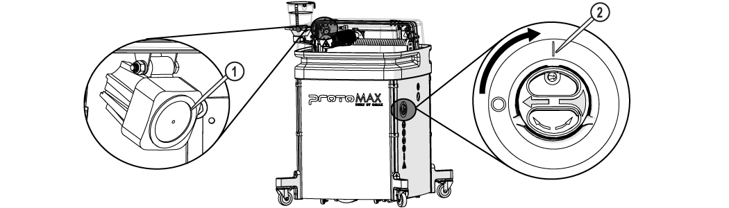
Figure 381
| 4. | Turn ON the incoming water supply. |
| 5. | Record the incoming water pressure (Figure 382). |
The incoming water pressure should be 45–85 psi.

| 6. | Open the software. |
| 7. | Click the to home the machine. |
Home is required after every power cycle. For example, when the main power switch is turned OFF and then turned back ON, during power outages, or the main power cord is disconnected.

Figure 383
| 8. | Conduct a nozzle test without abrasive. |
| a. | Open and secure the lid. |
Use care when opening or closing the lid to avoid injury. Keep hand, fingers, or body part away from the side of the table when closing the lid. Never let the lid free-fall.

Figure 384
| b. | Remove the abrasive feed tube from the nozzle and place it over the top of the Y-axis [1]. |

Figure 385
| c. | Verify the mixing tube is properly seated and secured in the nozzle body. |
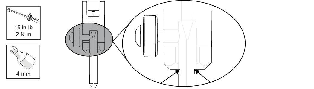
Figure 386
| d. | Place the nozzle splash guard [1] on the mixing tube [2] with the cup folded up. |

Figure 387
| e. | Position the nozzle in the center of the tank, between two slats using the , buttons or keyboard arrow keys. |

Figure 388
| f. | Lower the nozzle to within 1 in. of the surface of the water. |
Always hold the nozzle when loosening the hand knob. Do not let the nozzle fall and strike the cutting deck slats or material to avoid damage to the nozzle and/or nozzle components.
| g. | Close the lid. |
| h. | Click [1]. |

Figure 389
| i. | In Test Operations, select Test Cutting Head (Pump, Jet, and Abrasive), and click . |

Figure 390
| j. | Click . |

Figure 391
| k. | Click when the test is complete. |
| 9. | Fill the hopper with garnet abrasive. |
| a. | Remove the hopper lid. |

Figure 392
| b. | Pour the garnet abrasive through the garnet abrasive screen into the hopper. |
Gently tap the hopper side to evenly settle the garnet abrasive in the hopper.

Figure 393
| a. | Replace the hopper lid. |

Figure 394
| 10. | Conduct a nozzle test with abrasive. |
Use care when opening or closing the lid to avoid injury. Keep hand, fingers, or body part away from the side of the table when closing the lid. Never let the lid free-fall.
| a. | Open the lid. |
| b. | Visually check the condition of the garnet abrasive feed tube, replace as needed. |
| c. | Connect one end of the garnet abrasive feed tube to the garnet abrasive feed block [1] and connect the other end to the nozzle [2]. |
Bacteria in the tank water can build up. A minor break in the skin can introduce harmful bacteria into a wound. Always wear protective gloves if you have cuts or open wounds on your hands. When setting up material for cutting, wear gloves that provide protection against sharp metal edges.
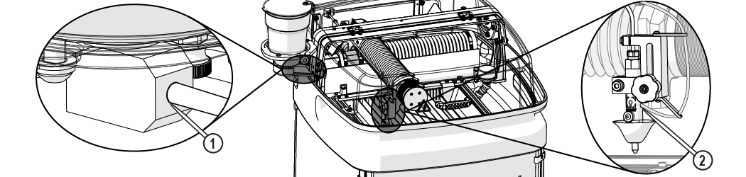
Figure 395
| d. | Open and use the , buttons [1] or keyboard arrow keys to position the nozzle between two slats. |

Figure 396
| e. | Lower the nozzle to within 1 in. (3 cm) of the surface of the water, if needed. |
Always hold the nozzle when loosening the hand knob. Do not let the nozzle fall and strike the cutting deck slats or material to avoid damage to the nozzle and/or nozzle components.
| f. | Click Test [1]. |
Figure 397
| g. | In Test Operations, select Test Cutting Head (Pump, Jet, and Abrasive), and click . |
Figure 398
| h. | Click . |
Figure 399
| 11. | Observe the garnet abrasive tube [1] at the hopper to verify the garnet abrasive is flowing, then click when the test is complete (Figure 400). |
The garnet abrasive flow is fast and hard to see. The sound increases indicating garnet abrasive is flowing.

| 12. | Inspect the nozzle [1] and all visible high-pressure plumbing [2] connections for leaks. |
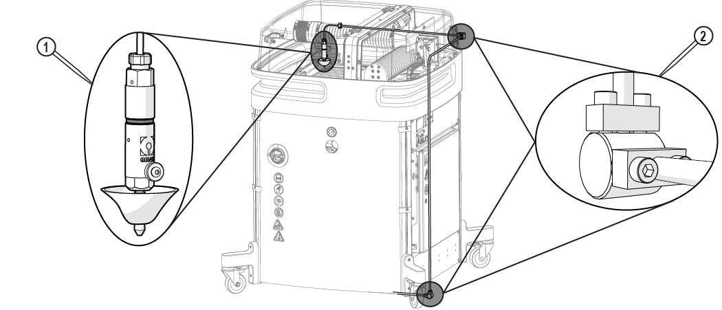
Figure 401
| 13. | Open and configure the kerf check sample file. |
 Cutting Best Practices and How to Cut the Kerf Check Part
| a. | In MAKE, open and configure the kerf check sample file. |

Figure 402
| b. | Open and secure the lid. |
Use care when opening or closing the lid to avoid injury. Keep hand, fingers, or body part away from the side of the table when closing the lid. Never let the lid free-fall.
Figure 403
Bacteria in the tank water can build up. A minor break in the skin can introduce harmful bacteria into a wound. Always wear protective gloves if you have cuts or open wounds on your hands. When setting up material for cutting, wear gloves that provide protection against sharp metal edges.
| 14. | Load and secure the material on the cutting stage. |

| 15. | Set the nozzle standoff at the highest point on the material. |
Always hold the nozzle when loosening the hand knob. Do not let the nozzle fall and strike the cutting deck slats or material to avoid damage to the nozzle and/or nozzle components.

Figure 405
| 16. | Position the nozzle at the path start. |
To extend the life of the catcher tank, cut towards the center of the tank. Continuous cutting at the outer edges of the cutting envelop may allow the jet stream to wear through the sides of the catcher tank.
| 17. | Close the lid. |
Use care when opening or closing the lid to avoid injury. Keep hand, fingers, or body part away from the side of the table when closing the lid. Never let the lid free-fall.
| a. | Lift the lid and push the support arm towards the back. |

Figure 406
| b. | Lower the lid to the catcher tank. |
| 18. | Perform a dry run. |
| a) | Open and configure (set the material type and thickness) for the machine tool path for the part. |
Figure 407
| b) | Click Go home [1] to move the nozzle to the Path Start Home position, if needed. |

Figure 408
| c) | Click to display the Path Control dialog box. |

Figure 409
| d) | Right-click the button to display a list of dry run options. |
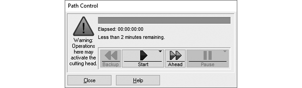
Figure 410
| e) | Click . |
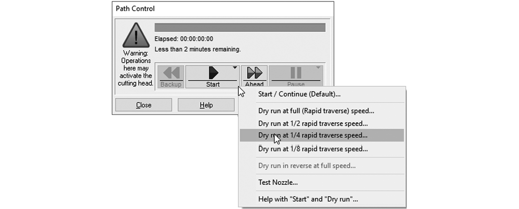
Figure 411
| f) | At any time, click if potential problems are seen during the dry run process to stop nozzle movement. |

Figure 412
| g) | When the dry run is finished, click the button to close the Path Control dialog. |

Figure 413
| 19. | Click in the Path Start dialog box to move the nozzle to the path start point. |
| 20. | Fold down splash guard cup. |
| 21. | Adjust the tank drain [1] and fill the tank with water above the material (if possible). |
To extend the life of the catcher tank, cut towards the center of the tank. Continuous cutting at the outer edges of the cutting envelop may allow the jet stream to wear through the sides of the catcher tank.
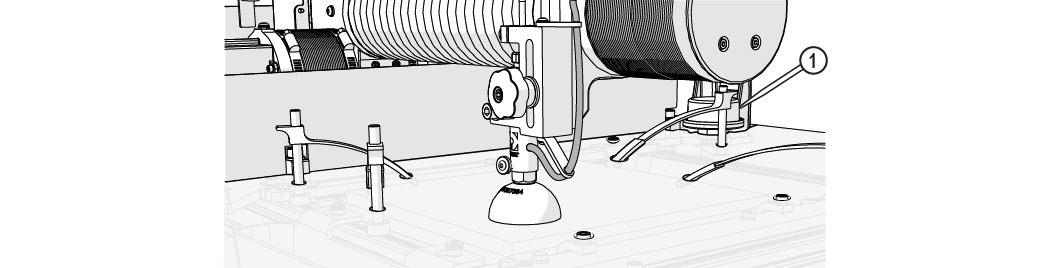
Figure 414
Cut parts under water when possible. Cutting under water lowers the noise level and reduces the mist and splash created by the water and abrasive. Cutting under water also helps the garnet bins collect cutting debris instead allowing the debris to settle in the tank, which makes tank cleaning easier.
| 22. | Close the lid. |
| 23. | Cut the part. |
| a. | Click Begin Machining [1]. |

Figure 415
| b. | Click . |
Figure 416
| 24. | Check the cutting water pressure and compare to the recorded incoming water pressure. |
If the cutting water pressure is 25 psi or lower, the water filter should be changed (see 401440-EN Maintenance, ProtoMAX).
| 25. | Adjust the tool offset [1] if needed, see Measuring the Abrasivejet Kerf. |
Figure 417