
________________________________________
Tool Path
The tool path is used by MAKE to control the nozzle cut
The ultimate purpose of the LAYOUT software is to create a continuous tool path. Gaps in the tool path can cause problems. For example, if lines don't quite meet at a corner, the tool path will be interrupted. Other CAD software programs, whose object is solely to make a picture, often create gaps. The LAYOUT software works to help you avoid such problems.
The tool path is saved in an OMX file and contains a series of commands for moving the abrasivejet machining head. LAYOUT and MAKE can also display the tool path on-screen, including the tool offset.
In the following figure, the tool path starts in the upper left corner and ends in the upper right corner. The bright purple line represents the perimeter of the part to cut in LAYOUT, while the thicker, darker line includes the tool offset. (The abrasivejet wears away some material as it machines.) Notice that you can start at the beginning of the tool path and follow it all the way through without interruption, until you reach the end.
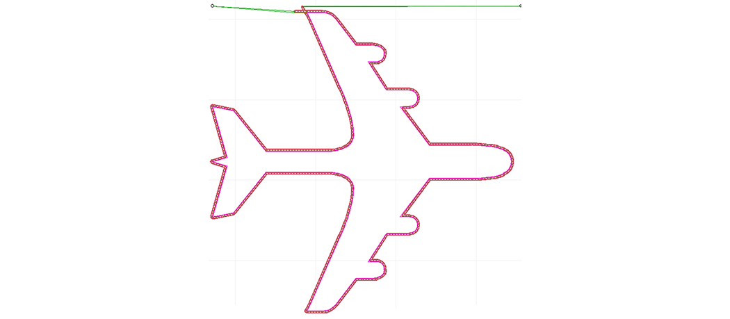
An example tool path
Notice also that the "start" of the tool path is somewhat arbitrary and is defined when the tool path is created. For this part, the tool path could just as easily have started in the upper right and ended in the upper left.