
________________________________________
Intelli-TRACE™
Automatically trace bitmap images into LAYOUT format
Intelli-TRACE™ is a command that can automatically trace a photograph or bitmap image and convert it to a LAYOUT drawing. This lets you take an image from a scanner, a digital camera, or even the Internet and quickly convert it to a tool path.
Intelli-TRACE lets you go from an image to a part
Intelli-TRACE has higher minimum system requirements than the rest of LAYOUT. On computers that do not meet the requirements, it will not run. If your computer barely meet the requirements, some features may be slightly crippled (in particular the pre-smoothing feature). The minimum system requirements are:
- Screen resolution of 1024x768 or higher
- At least 256 MB of available RAM. When working with larger images, more memory is often required for full functionality.
The Intelli-TRACE command supports the following bitmap formats:
*.tif; *.gif; *.jpg; *.pcx; *.bmp; *.ico; *.cur; *.png; *.emf; *.tga; *.pxm; *.wbmp; *.jp2; *.j2k; *.dcx; *.crw
You can also use the following movie file formats:
*.avi;*.mpg;*.wmv
When you use a movie format, the first frame of the movie file is loaded and displayed.
PDF files are also indirectly supported with the Image Tracing. To trace a PDF file, use “Import from other CAD” to open the PDF. LAYOUT will automatically recognize vector data, and convert it to lines and arcs for you. The remaining raster information is then automatically loaded as reference or to use with either manual or automatic image tracing on.
This also gives you a method to work with images in movie files. There are utilities that can convert movies to animated GIF files (such as GIF Construction Set by Alchemy Mindworks). Once converted, you can locate the frame you want to use and load it.
How to Use Intelli-TRACE
Intelli-TRACE uses a "wizard" model, which guides you step-by-step through the process of tracing images. As you proceed through each step, you can see your progress by looking at the tabs along the top of the screen. Once you are familiar with how the command works, you can use the tabs along the top to immediately jump to any step in the process.
The tabs along the top show your progress in the process
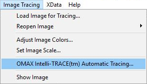
1) On the Image Tracing menu, choose the Intelli-TRACE option.
At the end of the tracing process, you'll have the option to replace the existing LAYOUT drawing or add the new trace to the existing drawing.
2) The Opening page appears.
It may take several seconds for this screen to appear--an animated cursor indicates that the program is still loading. This screen explains what Intelli-TRACE is and provides some basic tips. You can click on "Bypass Welcome screen in the future" to skip this screen the next time you run this command. (To view the Welcome screen again, just click on the tab and un-check this option.)
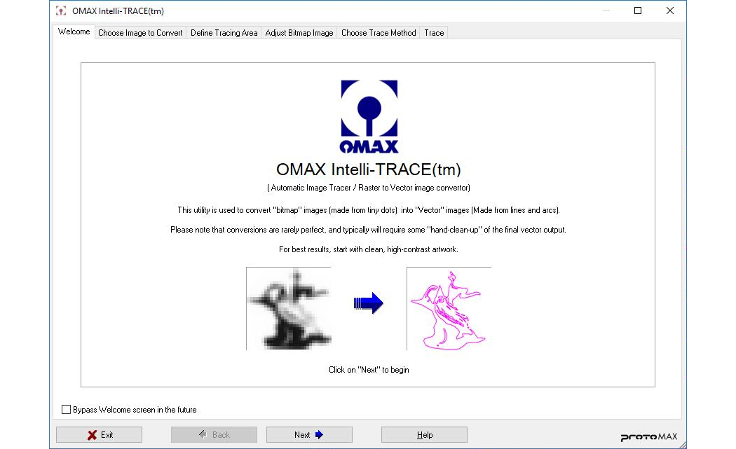
This screen appears the first time you run the Intelli-TRACE command
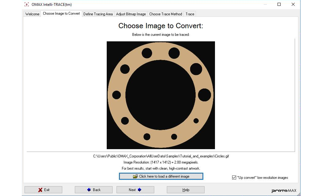
3) The "Choose Image to Convert" screen appears. If the image you want to convert does not appear on the screen, then click on the button near the bottom to load a different image. Click on the Next button when you have the image loaded.
If an image is already loaded for manual tracing, selecting Intelli-TRACE will automatically load the image.
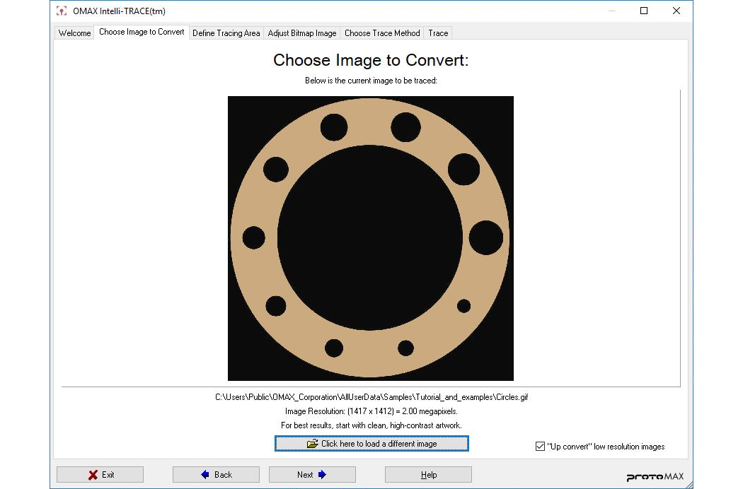
Choose the image you want to use in LAYOUT on this page
"Up convert" Low Resolution Images
When this box is checked, images of less than 750,000 total pixels (low resolution images) are automatically up converted. This option smooths out low resolution images to result in a better final trace, as shown in the following images. Note that it can take as long as a minute to up convert some images. When you don't want the smoothing effect, simply uncheck the box.
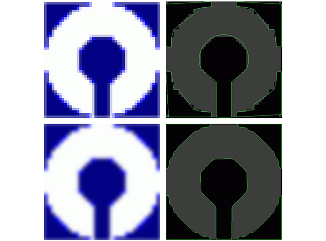
The top row shows the raw image and the resulting trace; the second row shows the smoothed image and resulting trace
Up converting images does not provide as good a result as starting with a good scan, but it can help when you cannot get a better scan. Note that up converting may interfere with Intelli-TRACE's ability to recognize circles.
4) You now define the area to be traced (if necessary). Click once to set the one corner of the area to trace and a second time to choose the opposite corner. To change your choice, select a new area to trace.
If the picture you are tracing has other objects in it, you can save time and trouble by choosing only the image you are interested in. In the image shown below, for example, the only area of interest is the picture of the dragon, so the area to be traced is restricted to just that section.
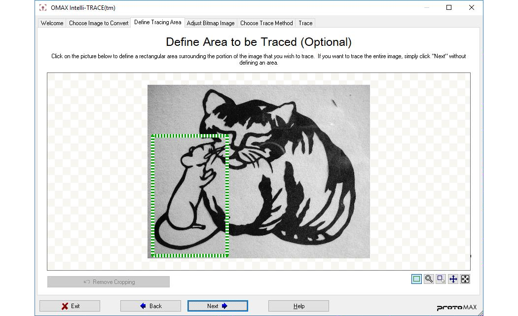
You can trace only part of a picture by defining an area to be traced
Note that again, this is a way to correct for a less-than-perfect photograph or image. In the case above, not only is the area of interest only part of the picture, but the picture is at an angle, which will skew the result. It would be much better to get a photograph that contained only the dragon at a straight-on angle.
Remove Cropping
After you move to the next step, you can return to the this screen to adjust the trace area. When you do so, the cropped image is displayed. For example, after defining the traced area in the dragon picture above, if you go to the next step and then return to this screen, you'll see the image shown below.
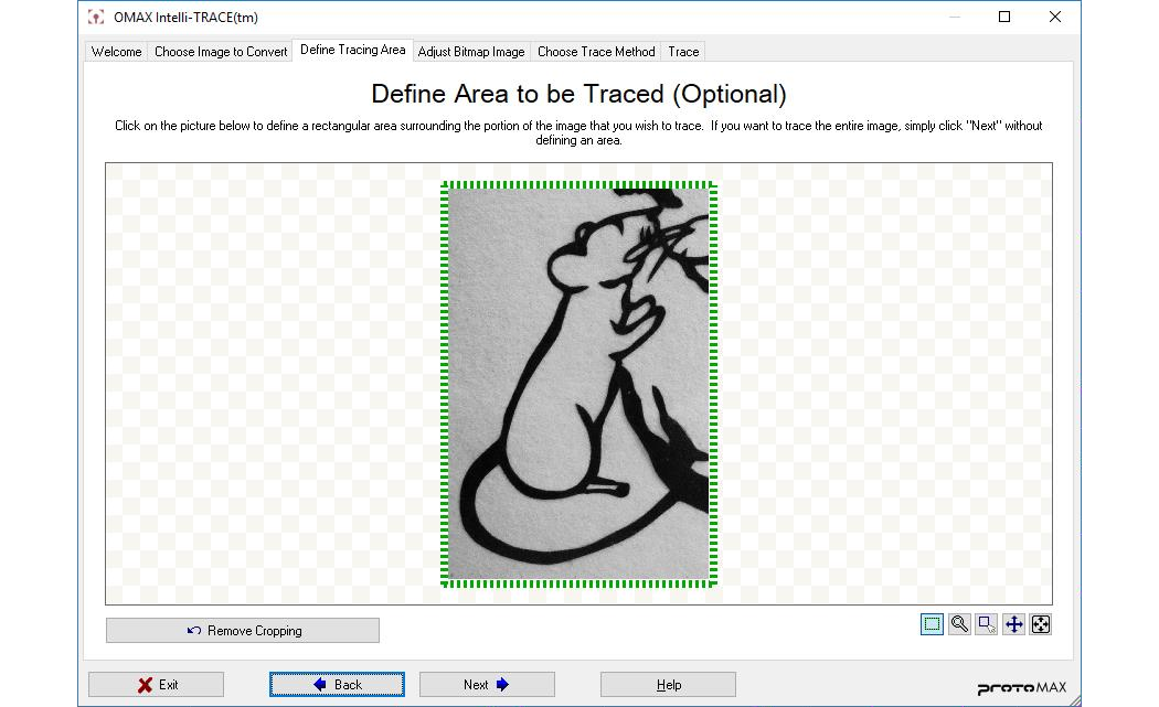
When you return to this screen, the cropped image appears
To restore the entire image, click on the Remove Cropping button in the lower left corner. (This button is only available if you leave and return to this screen.)
Zooming In
You can zoom in on parts of the drawing using the toolbar in the lower right part of this display. The Area to crop button brings back the cropping function after you zoom in or out on the image.

Use these buttons to control the image display
5) The "Adjust Bitmap Image" screen appears. On this page, you can fine tune how your image is traced based on the colors and contrast of the original image.
The basic way to use this screen involves adjusting two settings: noise reduction and the black-and-white threshold.
Noise Reduction / Smoothing
The "Noise Reduction / Smoothing" slider removes speckles and noise from the image, as well as smoothing out any rough edges. This can have a dramatic result in the final traced image, but also reduces the accuracy of the trace. Use it sparingly for mechanical parts where tracing accuracy is more important.
Black / White threshold
The "Black/White threshold" controls when a pixel is considered "black" or "white."
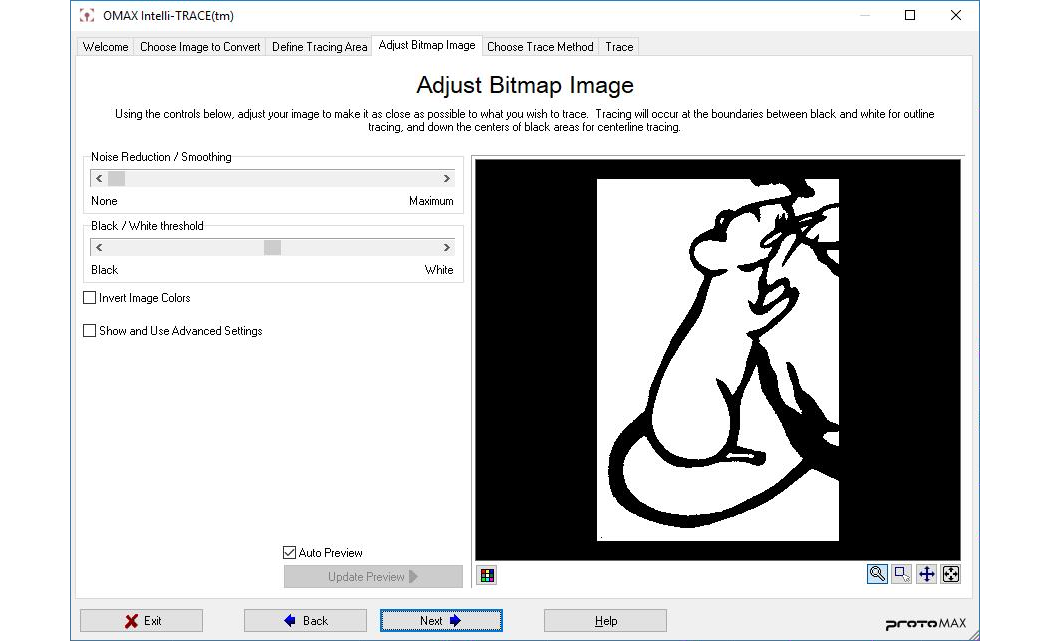
The image is displayed as black-and-white and you can adjust its appearance
Advanced Settings
The advanced settings are typically not needed, and will tend to be useful only in special cases, such as when an image is saturated with a particular color.
There are three advanced sliders, one for each primary color of red, green and blue. These sliders adjust the threshold for each color component individually. For example, if a particular pixel has a red component that is below the red slider threshold, then the red component of that pixel will be set to zero. If the red component is greater than the slider threshold, then it will be set to 100% brightness.
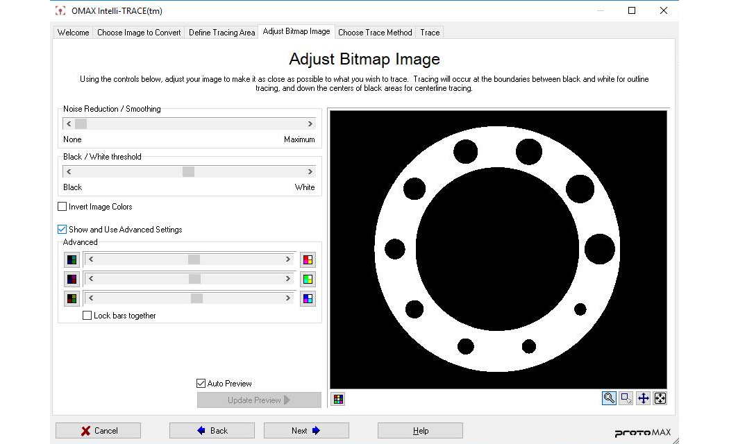
The advanced sliders let you adjust for individual colors
There is also a "Show as Color" button at the bottom left of the picture. This will display the image in color, which may help you decide which colors to remove or enhance.

Use the "Show as Color" button to display the image in color
6) The "Choose Trace Method" screen allows you to select the tracing method that works best for the image being used: Trace Outlines or Trace Centerlines.
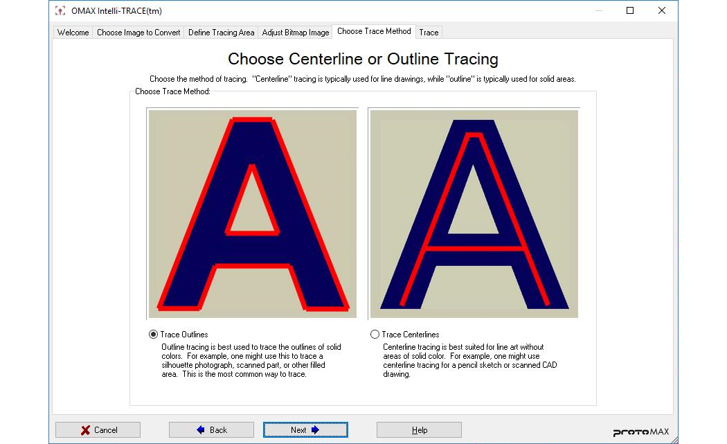
Choose a tracing method that works best for the image in use
Centerline tracing is used mostly with images composed of lines as opposed to images composed of solid filled areas. Some examples of where centerline tracing works best:
- Scanned CAD drawings (including black lines on white paper and blueprints)
- Artistic sketches without solid filling
Some tips for using Centerline Tracing:
- Experiment with deselecting the check box for "up convert low resolution images" (see "Choose Image to Convert" tab).
- Use the "Invert Image Colors" (see "Adjust Bitmap Image" tab) to invert the image in case the lines you wish to trace are light while the background is dark. (Centerline tracing ensures that the lines to be traced are dark with the background light.)
- • If you have an image that is a mix of elements that require both centerline tracing and outline tracing, you may wish to do two separate traces, then erase and recombine the results later in LAYOUT .
- Centerline tracing is significantly faster when up-converting is not used.
- For best results when using centerline tracing, use thin but unbroken lines for tracing. The thicker the line, the more ambiguous the center becomes and the worse the outcome.
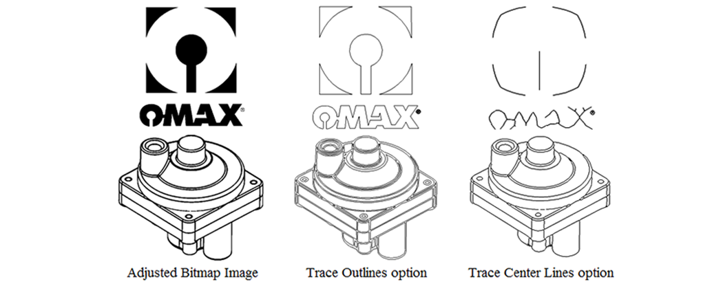
Examples that illustrate the differences between the two tracing methods: "Trace Outlines" and "Trace Center Lines"
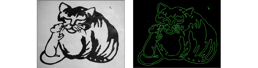
7) The "Configure tracing settings" page appears with the traced image shown in green. You can change the tracing settings on this screen--it has not yet been saved to your document. When you are satisfied with the results, click on the Finished button.
There are two general ways to change the settings: using a preset, or adjusting each setting individually. It is usually faster to use the preset, while adjusting individual settings gives you more control.
Using Presets
Presets are a good way to start out, and will probably take care of most images you need to scan. When comparing different methods, pay attention to small details and particularly small circular sections of the part, as these tend to be most affected by changing settings. The presets available are:
Generic
Good all-around setting
Geometric / Mechanical
Assumes circular objects are circles, and uses smooth arcs whenever possible
High-Contrast Artwork
Assumes the image is accurate and does less smoothing and circle detection
Smooth Arcs
Tries to create smooth lines whenever possible, but doesn't detect circles
Linear
Tends to draw everything using straight lines and only uses arcs when necessary
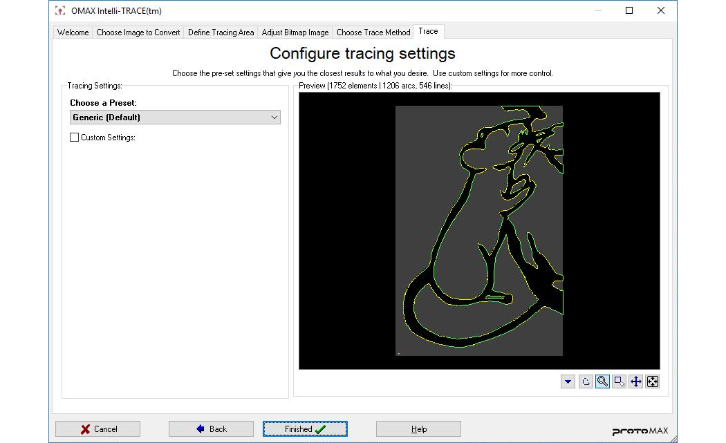
This screen shows the results of the tracing using the "Generic" preset
Changing Individual settings
When you check the "Custom Settings" box, a panel appears with a number of custom settings you can adjust. In most cases, you won't need to use these, as one of the presets will probably provide you with good results. These controls are provided to give you complete control over the tracing process if you want it.
Settings can be adjusted either using the slider or by entering a value directly in the edit box on the right. Note that you can enter larger values in the edit box than will be used by the slider. The slider only covers the most useful settings.
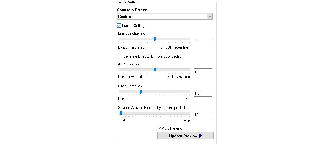
Clicking on Custom Settings displays these choices
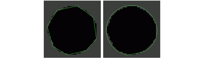
Line Straightening
The Line Straightening setting controls how exactly to fit the lines to the original image. As shown in the following figure, "exact" will try to match exactly the scan, while smoother settings will approximate the scan. Exact is most useful with high-quality images.

(left) "Exact" line straightening; (right) Smoother line
Generate Lines Only
When "Generate Lines Only" is checked, only lines will be used in tracing. No arcs or circles will be used (and the other settings pertaining to arcs and circles will be ignored).
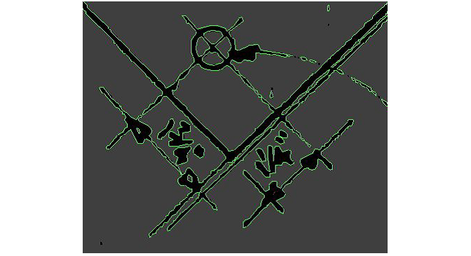
Arc Smoothing
"Arc Smoothing" controls how much curved areas are approximated with lines or arcs. When arc smoothing is set to a low value, circles and curved areas are approximated with many lines. You can turn on Highlight Arcs in Purple to check the results of this setting.
(left) low value of Arc Smoothing; (right) moderate Arc Smoothing
Circle Detection
The "Circle Detection" setting controls how sensitive the software is to detecting circles. Notice in the previous screen shot that the hole is only approximated by arcs, and that the bottom section is slightly deformed. With higher values of circle detection, the hole is detected as shown in the figure below. Detecting circles is most useful with mechanical parts, and least useful with artistic pieces. You can turn on Highlight Arcs in Purple to check the results of this setting.

When Circle Detection is turned up, this is detected as a true circle
Smallest Allowed Feature
The "Smallest Allowed Feature" sets how sensitive the tracing is to every pixel in the image. When set at small values, every feature is traced. Larger values (most useful with high-quality images) will discard small features as "noise" (dust, scratches, scanning imperfections). This setting will either trace a feature or not--it does not affect how accurately that feature is traced.
Auto Preview
The default setting is to display the results of changing a setting at once. When you are working with a large or complex image, this can result in a delay of several seconds while the changes are applied. In these cases, you can turn off "Auto Preview" and manually update the preview.
Display settings
You can click on the Display Settings button on the toolbar below the image to control some image settings. You display the original image in either color or Black-and-white, so you can check to see how accurate the tracing is. You can also dim the image to make it easier to see the trace, or turn off the image display altogether. You can also set the trace to display arcs in purple (leaving lines to display in green). This can be useful when you are adjusting the line and arc settings.


Click on the Display Settings button to view this menu
Highlighting arcs in purple
The Display settings let you turn on Highlight Arcs in Purple. This will use green for lines and purple for arcs in the display. This is useful for checking the results of the Circle Detection and Arc Smoothing settings.
8) When you click Finished, the trace is transferred to LAYOUT . You will probably need to edit the drawing to get the results you want, but you will have saved considerable work by using Intelli-TRACE.
If you have not registered MAKE on this computer, you will not be able to transfer the image to LAYOUT .
If you have a part already loaded in LAYOUT , you are prompted as to whether or not you want to replace it with the traced part or add the traced part to it. If you replace it, a new document is created and you'll want to save it to keep your work.
Tips for using Intelli-TRACE
- Not all images are suitable for scanning. Low resolution images, images with lots of noise, and images with low contrast are examples of images that may not give good results with Intelli-TRACE. The human eye is very good at dealing with these sorts of images, so manual tracing may give better results.
- Image tracing is never as good as getting the original drawing in vector format. When someone gives you a picture of a part (especially if it's clear that it's a printout from a drawing program) ask if you can get the original drawing. Chances are that LAYOUT will be able to directly import it, giving you a better quality result for less work.
When lines are encountered, they are outlined
- When the image is brought into LAYOUT , the scale will almost certainly be wrong. Use the Size command to make the drawing the desired size.
- Complex artwork will often include features that do not make sense to cut. Some thought and effort is needed with artistic pieces to make sure that the final result is what is intended.
- Some clean-up is often necessary to get good results when the tool offset is applied. In particular, watch out for sharp inside corners where there are tiny lines or arcs. Manually replace such features with larger arcs or lines for best results. For complex artworks, the amount of clean-up required may be considerable.
- Start with clean high-contrast artwork. The better the image, the better the result.
- Consider using manual Image Tracing for images where the edges are not well defined by high contrast, for some photographs, or for mechanical parts that have been scanned in when high precision is required.
- Color images work well for Intelli-TRACE automatic tracing. If you intend to make an inlayed part from multiple colors, however, manual tracing may be a better option, so that you have full control over which pieces are cut, and how they fit together.
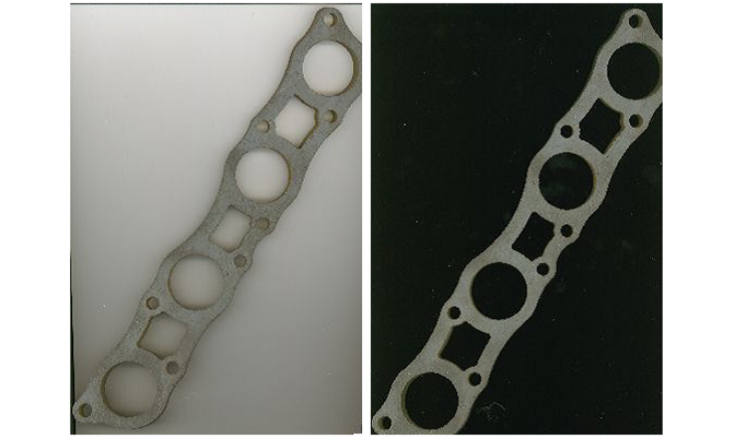
- When scanning mechanical parts, consider leaving the top of the scanner off, and scanning in a dark room. This will help over-expose the bottom of the part, and darken the shadows on the edges and the background, making it easier to trace the top of the part, without being confused by the edges.
The following images show two different scans of the same part. The left scan is not a good scan and will not trace well, because the shadows and reflections from the top of the scanner are of similar brightness to the part itself. The second part is much better, because the pure-black background makes it clear where the part stops and the background begins.
Use the display option to “Highlight arcs in purple” at the final tracing step (the “Trace” tab) to clearly show which entities have been converted to arcs and which remain as lines. Arcs appear in purple, and lines as green.