Config
Configures the appearance of LAYOUT
The commands controls how LAYOUT works, and the appearance of the screen.

Keyboard Shortcuts
. (period) - show dots
, (comma) - Toggle Snap Grid
! - Thick Lines
Show Dots
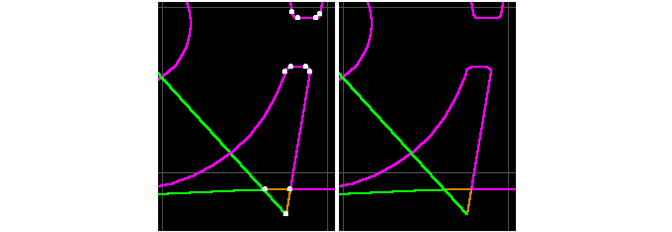
controls whether or not dots are shown at the endpoints of entities. With turned on, it is easier to see where each entity begins and ends.
If there are many entities, however, showing the endpoints can clutter up the screen and slow down redraw operations.

The figure on the right has Show Dots turned off
Show Table Area Grid
controls whether or not the white lines appear on the drawing table. These lines provide a guide for your parts, as well as a sense of the size of the part. Turning them off does not affect the part, and is strictly a matter of personal preference.
The spacing of the grid lines is controlled by in the command.
Enable Snap Grid
lets you turn on the "snap to" function. When this is on, LAYOUT will use the closest point on the snap grid when a new entity is drawn.
For example, if the snap grid is set to 1/10 in., when a new line is added, it will snap to one of the points (unless a Snap tool is used).
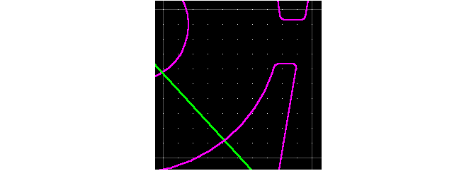
The spacing of the snap grid is controlled by in the command. The snap grid appears as a series of small white dots on the screen. The snap grid will not be visible unless you are zoomed in close enough.

The snap grid was set at 1/10 in.
Thick Lines
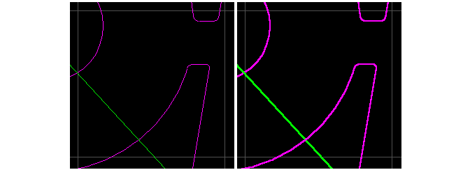
controls the appearance of the entities on the screen. When is turned on, the lines are drawn thicker to make them easier to see.
Turning on has no effect on a part, although it does slow down redraw. If you have a large part with many entities, you may want to turn off .

The figure on the right has thick lines turned on
Dim Leads and Traverses
The command makes these entities appear dimmer on the screen. For complex parts, this can make it easier to see the contours of the part.

Regular leads and traverses (left); when dimmed, it's easier to see the part (right)