Connect the High-Pressure Plumbing
| 1. | Verify the u-shape high-pressure nipple, gland nut, slotted collar, and collar are assembled and aligned. |
High-pressure nipples have left-hand threads, therefore when connecting components, turn clockwise to loosen and counter-clockwise tighten. Cross threading high-pressure connections may cause leaks and/or water damage from the leak(s).
Nipples contain small caps to protect the threading and keep debris from entering the high-pressure plumbing during shipment. The caps must be removed before assembling the high-pressure plumbing fittings. Do not use pliers to remove the black caps or cut the black caps from the nipple. Pliers and knives will damage the nipple threads causing leaks and/or water damage.
When preparing the ProtoMAX high-pressure tubing, it is extremely important to follow instructions. Some high-pressure tubing and fittings are pre-assembled. Fittings may need readjustment during installation to ensure proper seals and eliminate potential leaks. Use the provided stand-off tool to ensure the fittings are properly seated and sealed.
| a. | Rotate the nipple cap clockwise to remove it from the gland nut and verify there is no debris in the high-pressure tube. |

Figure 189
| b. | Verify the collar [1] is installed in the correct position using the stand-off tool [2]; adjust the collar to the correct depth if needed. |
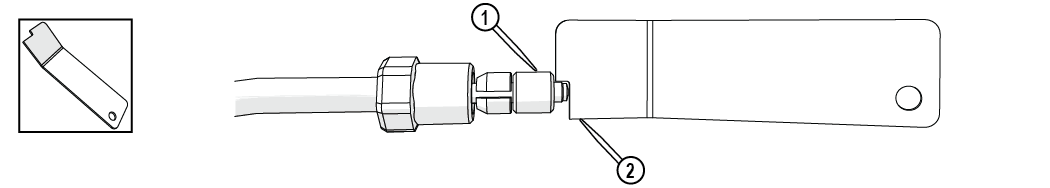
Figure 190
| 2. | Remove the bracket cap [1]. |
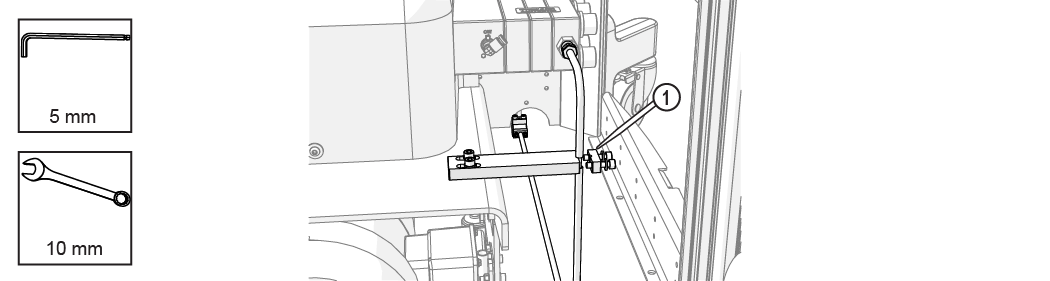
Figure 191
| 3. | Loosen the bracket. |
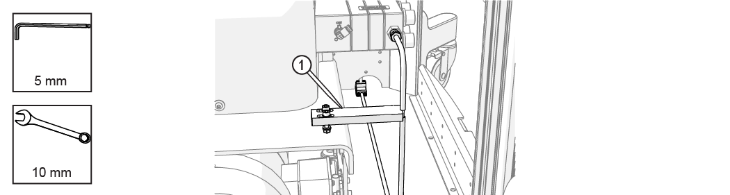
Figure 192
| 4. | Position the pump so the high-pressure plumbing is aligned vertically and horizontally, and the rear of the pump is 1–2 in. from the control cabinet. |

| 5. | Attach the assembled u-shape nipple to the pump high-pressure outlet OUT connection [1] and hand-tighten. |
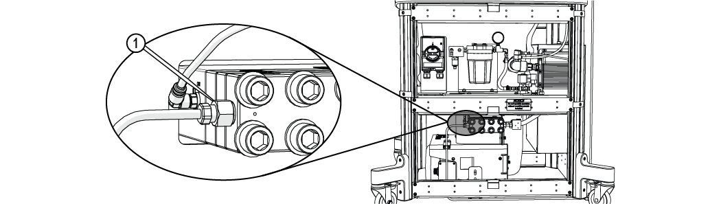
Figure 194
| 6. | Verify the gland nut is set approximately to the depth of the nozzle stand-off tool. |
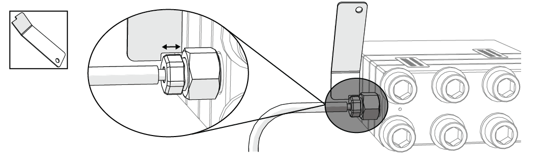
Figure 195
| 7. | Adjust the position of the bracket [1], then tighten the bracket. |
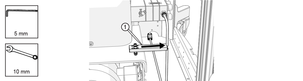
Figure 196
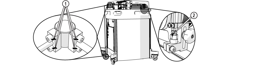
| 8. | Lock the pump wheels [1]. |
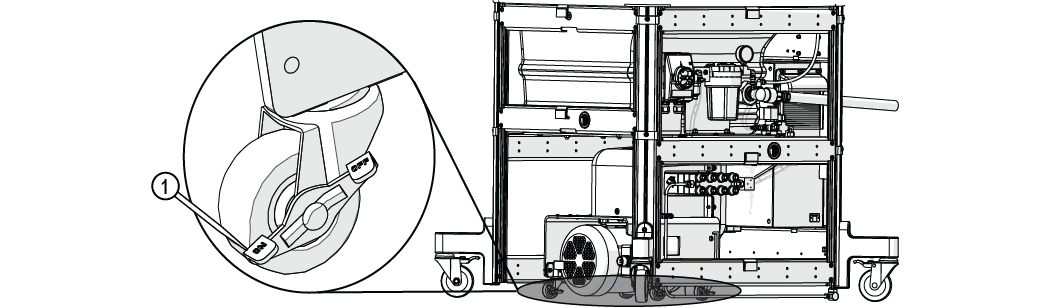
Figure 197
| 9. | Torque the pump connection. |
The jaws of the crowfoot must maintain a 90-degree angle to the horizontal axis of the torque-wrench handle throughout the torquing rotation. Other angles of orientation will alter the set torque.
Figure 198
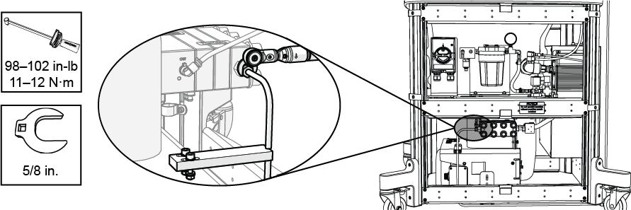
Figure 199
| 10. | Attach the bracket cap [1] and tighten. |
Ensure the flexible conduit is not trapped under the bracket.
Figure 200
| 11. | Verify the torque seals [1, 2] are not cracked or missing on all pre-assembled high-pressure connections and nozzle inlet body connection. |
Personal injury and/or damage may occur if high-pressure torque seals are cracked or missing. Contact Technical Support before operating the ProtoMAX if any high-pressure plumbing seal is cracked or missing.