Recover from a Nozzle Clog
 Recover from a Nozzle Clog
There are multiple scenarios resulting from a clog in the nozzle. The fix depends on how far water has traveled back up the abrasive feed tube and whether the water entered the abrasive hopper or not. In all scenarios, correct the condition that caused the nozzle to clog, such as wet garnet, a blocked orifice, a blocked mixing tube, or other before continuing operation.
| 1. | Remove the garnet abrasive feed tube from the nozzle assembly [2] and the garnet abrasive feed block [1]. |
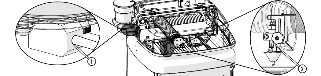
Figure 159
| 2. | Use clean, dry air to completely clear the clog from the abrasive feed tube. |
If the water entered the abrasive feed block:
| 3. | Remove the hopper splash guard. |
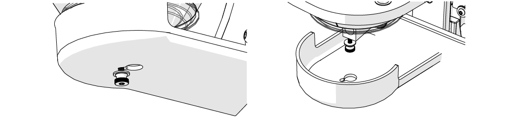
Figure 160
| 4. | Remove the hopper ground strap [1]. |
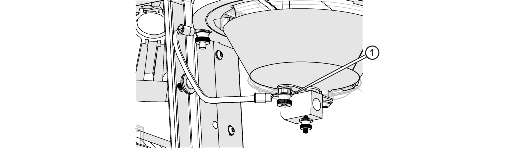
Figure 161
| 5. | Remove the abrasive feed block [2] and insert the red plug [1] to prevent garnet from pouring out from the bottom of the hopper assembly. |

Figure 162
| 6. | Use clean, dry air to completely blow out all debris, clumps, or clogs from the abrasive feed block. |
If the water entered the hopper assembly:
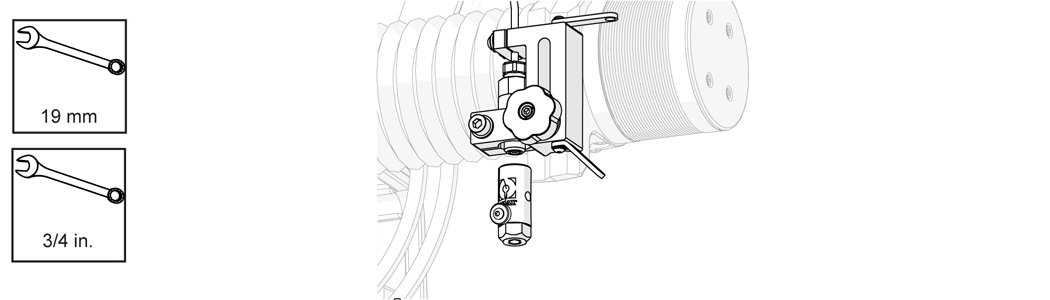
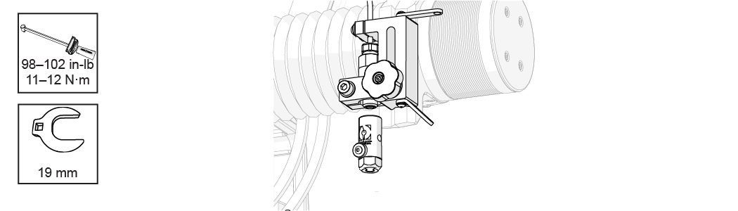
| 7. | Loosen the knob [1] and remove the hopper assembly from the hopper support plate. |

Figure 163
| 8. | Completely empty and wipe out the hopper. |
Make sure the hopper container is completely dry prior to filling with dry garnet abrasive. Do not reuse garnet abrasive. The hopper screen may not sufficiently remove moist clumps from the wet abrasive. Garnet that has been exposed to moisture will clump and cannot be reused. Garnet that has been exposed to moisture will result in additional clogging.
| 9. | Raise the Z-axis. |
| 10. | Remove the nozzle splash guard and mixing tube [1] from the nozzle body. |
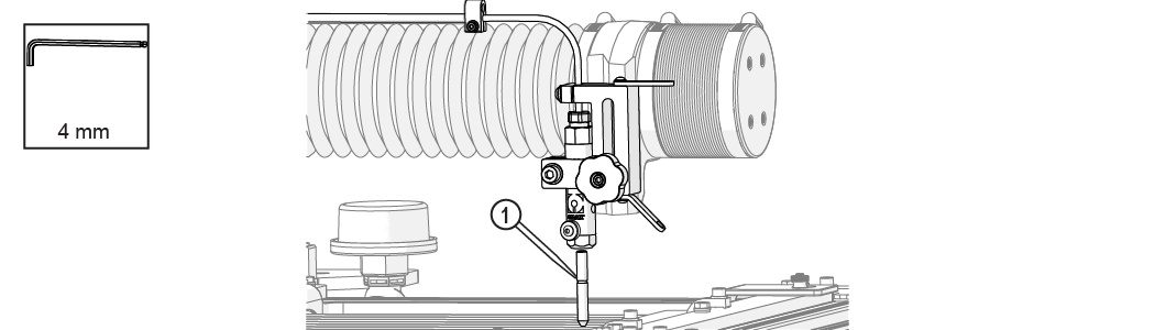
Figure 164
| 11. | Inspect the mixing tube to see if light is visible through the bore. |
If light is visible:
| 12. | Re-install the mixing tube [1] into the nozzle body. |
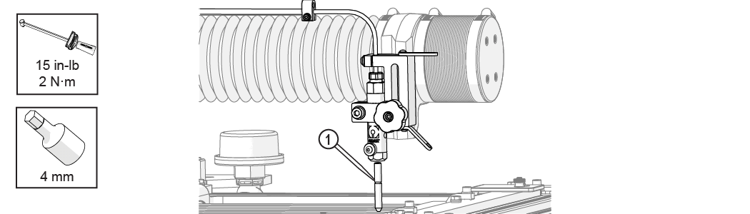
Figure 165
If light is not visible:
| 13. | Turn the mixing tube [1] upside down and insert it back into the nozzle body and tighten it. |
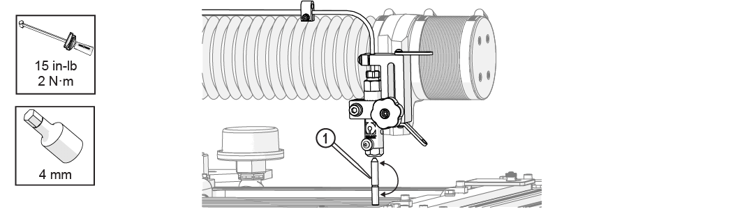
Figure 166
| 14. | Position the nozzle towards the center of the tank (off the material) between two slats. |
| 15. | Lower the Z-axis to approximately 1 in. (3 cm) above the water surface. |
| 16. | Close the lid. |
Use care when opening or closing the lid to avoid injury. Keep hand, fingers, or body part away from the side of the table when closing the lid. Never let the lid free-fall.
| 17. | Open the dialog box and run a nozzle test to clear the mixing tube. |
| 18. | Remove the mixing tube [1]. |
Figure 167
| 19. | Remove the nozzle body assembly from the nozzle inlet body. |
| 20. | Remove the orifice assembly [1] and inspect the chamber bore [2]. |
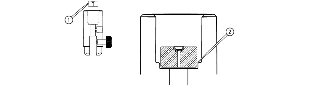
Figure 169
| 21. | Clean the orifice assembly and the nozzle body (including the air vent hole) thoroughly prior to reassembly. |
Do not use a brush or cotton swab or foam-tipped applicator to apply lubricants because they may leave fibers and plug the nozzle.
| 1. | Clean the inlet body threads by wiping with a clean rag. |
| 2. | Apply a light coat of Blue Goop to the second and third threads [1] of the inlet body, then spread the lubricant evenly around the inlet body threads. |
Use care when applying lubricants around high-pressure water routes. Lubricants can enter the high-pressure water system and clog the orifice and/or mixing tube.
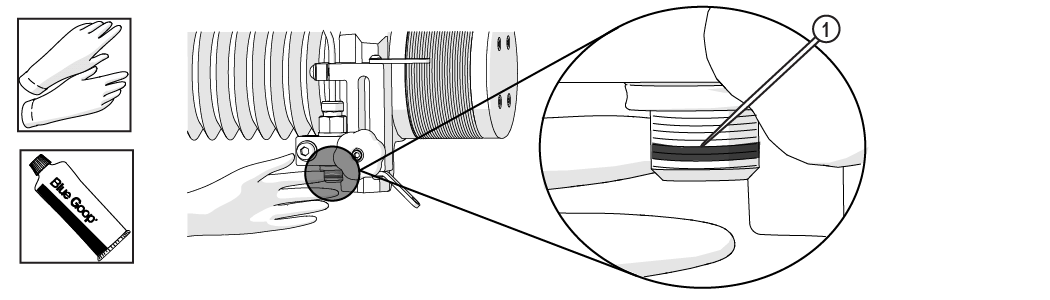
Figure 170
| 3. | Wipe the excess Blue Goop from the end of the inlet body [1]. |
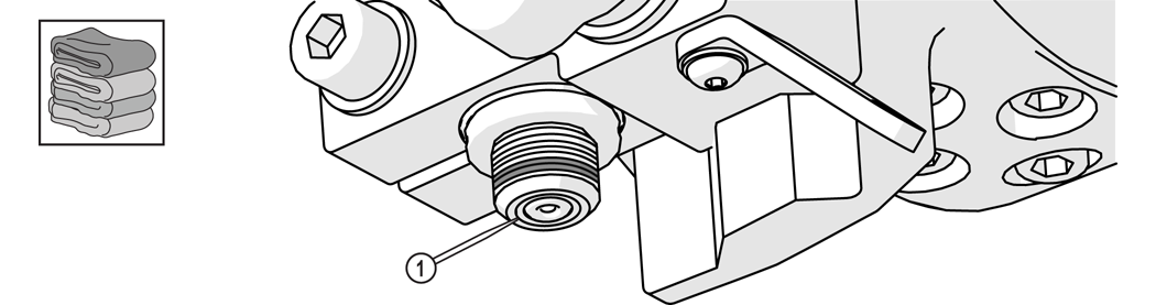
Figure 171
| 4. | Apply a light coat of Blue Goop to the first and second nozzle body threads [1], then spread the lubricant evenly around the nozzle body threads. |
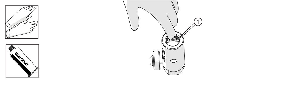
Figure 172
| 5. | Wipe the excess Blue Goop from the end of the nozzle body [1]. |
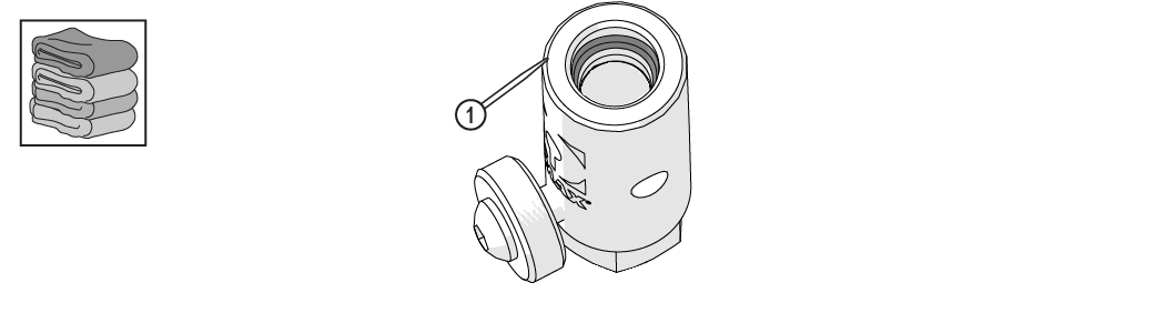
Figure 173
Once the nozzle is completely clean:
Always orient the orifice assembly so the brass [1] is visible from the top of the nozzle body. Inserting the orifice assembly in nozzle body in the incorrect orientation [2] may cause damage to the orifice assembly.

Figure 174
| 6. | Insert the orifice assembly [1] into the nozzle body and adjust the orifice to ensure the it is seated correctly in the chamber bore [2]. |
| 7. | Re-install the nozzle assembly on the nozzle inlet body. |
| 8. | Raise Z-axis and move the cutting head over the material. |
| 9. | Insert and the mixing tube. |
| 10. | Close the Path Control window. |
| 11. | Re-install the hopper and its components (abrasive feed block, feed tube, ground strap, and hopper splash guard. |
When installing the abrasive hopper, ensure the washer is located on the underside of the hopper splash guard.
| 12. | Fill the hopper with fresh, dry abrasive. |
| 13. | Connect the abrasive tube to the nozzle body. |
If an alert or fault message is displayed, reset the pump (see Reset the Pump).
| 14. | Attach the nozzle splash guard. |
| 15. | Set the nozzle stand-off. |
| 16. | Close the lid. |
Use care when opening or closing the lid to avoid injury. Keep hand, fingers, or body part away from the side of the table when closing the lid. Never let the lid free-fall.
To continue cutting the part, using MAKE:
| 17. | Click in the Path Start Home dialogue. |

Figure 177
| 18. | Right-click . |

Figure 178
| 19. | Click . |

Figure 179
| 20. | Move the cursor over the spot on the tool path slightly before the clog occurred and left click. |
| 21. | Click on Machine will now traverse into position dialog box. |

Figure 180
| 22. | Click to start cutting. |

Figure 181
If nozzle clogging continues, it may be necessary to replace the abrasive feed tube, the mixing tube, nozzle orifice, and/or nozzle filter as one or more of these components may be causing the problem.